
S7900 OddForm Insertion Machine Solution for Smart EMS THT PCB Assembly
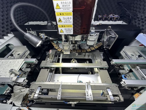
S7900 odd-form insertion machine: 2, 4 or 6 servo heads, 0.6-0.8 s per component, 0.6-2.0 mm board, 0-360 degree insertion, four lead-clinching patterns and bowl, tape, tube and tray feeders on one platform. Includes a 36-line THT BOM split and a three-document disclosure table.
Connectors, relays, transformers, trimmers, bulk capacitors, DIP ICs and spade terminals — the parts that arrive in bowls, tubes and trays and still get placed by hand. The S7900 picks them with a vacuum nozzle or an air gripper, checks polarity and lead condition with bottom vision, inserts at any angle from 0 to 360 degrees, and clinches the leads in one of four patterns so nothing floats into the wave.
Key features
Manual insertion does not scale with the order book
The customer solution document behind this page opens with the same list every EMS plant recognises: labour cost rising year on year, a shrinking general labour pool, skilled operators who take time to train, quality that drifts with the shift, capacity that cannot be promised, and floor space consumed by benches. None of those are insertion defects. They are the cost of running a manual process…
Odd-form packaging is inconsistent by design
A single odd-form BOM mixes five supply formats — loose bulk, ammo pack, tape, tray and tube — because that is how the component makers ship. A machine that only takes tape is not an odd-form machine. The S7900 platform is documented with all four feeder families on one base: bowl for bulk, tape for taped parts, tube for relays and ICs, and tray for connectors and transformers, with a…
Floating parts are a wave-soldering defect, not an insertion defect
A part that is inserted but not secured can lift during wave soldering, and the fault shows up downstream as a bridge, a void or an open. The S7900 addresses it at the insertion head: an optional bottom clinching unit bends the leads after insertion so the part cannot move. Four bend patterns are documented — outward, inner, circular and two turns — and the specification gives lead diameter…
Specifications
Figures as published in Southern Machinery documents. Where two sources disagree, both values are shown with their source.
| Size (L × W × H) | 1050 × 1680 × 1870 mm · 1300 × 1700 × 2000 mm · 1550 × 1900 × 2100 mm · 1300 × 1700 × 2000 mm · 1550 × 1900 × 2100 mm |
|---|---|
| Weight | 1250 kg · 1650 kg · 1750 kg · 1730 kg · 1800 kg |
| Operation system | Windows |
| No. of door | Single side · Double side · Single side |
| Safety grating (door) | Standard configuration |
| Air supply | 0.5 – 0.65 MPa (ANR) |
| Max power | 4.5 kW · 5.4 kW · 6.6 kW · 5.2 kW · 6.3 kW |
| Run power | 2 kW · 3.3 kW · 3.5 kW · not stated in the catalog · 3.5 kW |
| No. of insertion heads | 2 · 4 · 4 · 6 · 6 |
| Max component size | φ50 (35 × 35) mm · φ30 (17 × 17) mm · φ50 (35 × 35) mm |
| Component height | ≤ 25 mm · ≤ 30 mm · ≤ 25 mm · ≤ 20 mm · ≤ 30 mm |
| Component feeding type | Nozzle / clamp |
| Speed per component | 0.8 s · 0.7 s · 2 s (with lead clinching) · 0.6 s · 0.6 s |
| Placement accuracy (CPK ≥ 1.0) | ± 0.06 mm · ± 0.06 mm · ± 0.05 mm · ± 0.06 mm · ± 0.05 mm |
| Insert power | ≤ 29.4 N · ≤ 98 N · ≤ 29.4 N · ≤ 29.4 N · ≤ 29.4 N |
| Insertion direction | 0 – 360° |
| Insertion component / object | Connector, switch, socket, transformer, coils, ports, capacitors, resistors, IC, etc. |
| PCB size (L × W) | 70 × 70 ~ 300 × 500 mm · 70 × 70 ~ 410 × 500 mm · 70 × 70 ~ 450 × 400 mm · 70 × 70 ~ 410 × 350 mm · 70 × 70 ~ 410 × 360 mm |
| Carrier size (L × W) | max 350 × 500 mm · max 500 × 500 mm · max 500 × 550 mm · max 410 × 350 mm · max 410 × 360 mm |
| PCB thickness | 0.6 – 2.0 mm |
| Conveyor space | 25 / 20 mm · 30 / 20 mm · 25 / 20 mm · 20 / 20 mm · 30 / 20 mm |
| Max PCB weight | 5 kg · 2 kg · 5 kg |
| PCB included side width | ≥ 5 mm |
| PCB fixed type | Servo / cylinder clamping |
| Conveyor type | Chain · Belt · Chain |
| PCB direction | R to L / L to R |
| Conveyor section | 3 |
| Conveyor adjusting | Auto |
| Conveyor height | 750 ± 20 mm · 900 ± 20 mm · not applicable |
| Lead clinching unit | not applicable · not applicable · standard · not applicable · option |
| SMEMA / MES connection | Standard configuration |
| Vision — mark CCD (top) | 1 |
| Vision — component CCD (bottom) | 2 · 4 · 4 · 2 · 6 |
| 201 radial tape feeder | 4 · 6 · 6 · 10 · 6 |
| 218 radial tape feeder | 4 · 6 · 6 · 10 · 6 |
| 207 radial tape 90° feeder | 4 · 6 · 6 · 10 · 6 |
| 259 radial tape feeder | 4 · 6 · 6 · 10 · 6 |
| 254 radial tape feeder | 6 · 12 · 12 · 20 · 12 |
| 202 axial tape feeder | 4 · 6 · 6 · 10 · 6 |
| 222 tube feeder | 6 · 12 · 12 · 20 · 12 |
Show 3 more rows
| 203 tube feeder | 4 · 6 · 6 · 10 · 6 |
|---|---|
| 205 bowl feeder | 4 · 4 · 4 · 8 · 4 |
| Tray feeder | 1 · 1 · 1 · 2 · 1 |
Models, comparisons and open points
The same board, read by packaging instead of by function (5 rows)
| Supply format | Lines | Feeder family that handles it | Documented feeder figures |
|---|---|---|---|
| Loose bulk | 17 | Bowl feeder | 4 per machine on S7900-II / IV / VI-P, 8 on S7900-VI |
| Ammo pack (axial tape) | 9 | Axial tape feeder | 4 to 10 stations depending on model |
| Tape | 5 | Radial tape feeder, six widths | 4 to 20 stations per width |
| Tray | 3 | Tray feeder, single or automatic | 1 on S7900-II / IV / VI-P, 2 on S7900-VI |
| Tube | 2 | Tube feeder, two widths | 4 to 20 stations depending on model |
The same board, read by packaging instead of by function (36 rows)
| Line | Component description as received | Reference | Supply format | Proposed machine |
|---|---|---|---|---|
| 01 | CAP ALUM 68µF 20% 250V RADIAL | C9 | Tape | Odd-form inserter |
| 02 | CAP CER 3300pF 1kV 10% RADIAL | C45 | Tape | Odd-form inserter |
| 03 | CAP CER 2200pF 440VAC 20% RADIAL | C46 | Tape | Odd-form inserter |
| 04 | CAP ALUM 330µF 20% 25V RADIAL | C47 | Bulk | Odd-form inserter |
| 05 | CAP ALUM 2200µF 20% 25V RADIAL | C48 | Bulk | Odd-form inserter |
| 06 | CAP ALUM 10µF 20% 25V RADIAL | C50 | Tape | Odd-form inserter |
| 07 | Noise suppression cap 0.22µF 275Vac 10% P=15.0mm | C63 | Bulk | Odd-form inserter |
| 08 | Noise suppression cap 0.01µF 275Vac 10% P=10.0mm | C98 | Bulk | Odd-form inserter |
| 09 | Connector P=2.5mm 2-pin 1-row vertical unshrouded | J12 J18 | Bulk | Odd-form inserter |
| 10 | Connector P=2.5mm 4-pin 1-row right-angle unshrouded | J3 | Bulk | Odd-form inserter |
| 11 | Connector P=2.5mm 5-pin 1-row right-angle unshrouded | J6 | Bulk | Odd-form inserter |
| 12 | Connector P=2.5mm 4-pin 1-row vertical unshrouded | J8 | Bulk | Odd-form inserter |
| 13 | Spade terminal | J15 J20 | Bulk | Odd-form inserter |
| 14 | Connector P=2.5mm 2-pin 1-row right-angle hook, ivory | J19 | Bulk | Odd-form inserter |
| 15 | Connector P=2.0mm 34-pin 2-row right-angle latch type | J22 | Tray | Odd-form inserter |
| 16 | Connector P=2.0mm 5-pin 1-row vertical white | J27 | Bulk | Odd-form inserter |
| 17 | Relay 12Vdc SPDT 16A flux protection | K2 | Tube | Odd-form inserter |
| 18 | Varistor 212V 2.5kA disc 10mm | MOV1 | Tape | Odd-form inserter |
| 19 | Sensing gauge | PS1 | Tray | Odd-form inserter |
| 20 | Transformer | T1 | Tray | Odd-form inserter |
| 21 | IC off-line switch PWM, 8-pin DIP | U6 | Tube | Odd-form inserter |
| 22 | Trimmer potentiometer 500Ω 30% 0.1W | VR1 | Bulk | Odd-form inserter |
| 23 | Trimmer potentiometer 100Ω 30% 0.1W | VR2 | Bulk | Odd-form inserter |
| 24 | 2.5mm vertical header, 2-pin | J7 | Bulk | Odd-form inserter |
| 25 | 2.5mm vertical header, 4-pin | J11 | Bulk | Odd-form inserter |
| 26 | Connector P=2.5mm 2-pin 1-row right-angle shrouded | J2 | Bulk | Odd-form inserter |
| 27 | DIODE GEN PURP 400V 1A DO-204AL | D1 D2 D3 | Ammo | Axial inserter |
| 28 | DIODE SCHOTTKY 80V 5A DO-201AD | D10 | Ammo | Axial inserter |
| 29 | DIODE GEN PURP 1kV 1A DO-41 | D11 | Ammo | Axial inserter |
| 30 | TVS diode, axial | D72 | Ammo | Axial inserter |
| 31 | RES AXIAL 100Ω 5% 1/4W | R21 | Ammo | Axial inserter |
| 32 | RES RADIAL 2Ω 5% 3W | R26 | Ammo | Axial inserter |
| 33 | RES 0.0Ω 3A jump, axial | R27 | Ammo | Axial inserter |
| 34 | (no description in the source file) | R55 | Ammo | Axial inserter |
| 35 | RES AXIAL 100kΩ 5% 1W | R72 | Ammo | Axial inserter |
| 36 | HARNESS, GROUND CRIMP, PCBA | AC(G) | Bulk | Manual — not a feeder component |
Where the documents disagree — printed side by side, not averaged (15 rows)
| Item | Customer solution document | S7900 catalog 2025 | Precision S7900 presentation |
|---|---|---|---|
| No. of insertion heads | 6 heads (3 + 3 layout) | 2 / 4 / 4 / 6 / 6 — one value per model | not stated in the catalog |
| Speed | 2,400 CPH (conditional) | 0.6 – 0.8 s per component | 4,700 CPH max |
| Placement accuracy | 0 – 360°, ± 0.1° adjustable (orientation only) | ± 0.05 / ± 0.06 mm, CPK ≥ 1.0 | ± 0.06 mm |
| Max PCB size | L490 × W420 mm | 70 × 70 ~ 450 × 400 mm (largest model) | 480 × 390 mm |
| Min PCB size | L50 × W50 mm on one page, L60 × W60 mm on another — the document disagrees with itself | 70 × 70 mm | not stated in the catalog |
| Machine size (L × W × H) | W1670 × D1620 × H1690 mm | 1050 × 1680 × 1870 mm to 1550 × 1900 × 2100 mm | not stated in the catalog |
| Machine weight | approx. 1300 kg | 1250 – 1800 kg depending on model | not stated in the catalog |
| Max PCB weight | 3 kg | 5 kg on II / IV / VI-P, 2 kg on VI | not stated in the catalog |
| Conveyor height | 930 ± 30 mm | 750 ± 20 mm on II / IV, 900 ± 20 mm on IV-P | not stated in the catalog |
| Power | Single phase AC 200 – 220 V, 50/60 Hz, 2 kW | Max 4.5 – 6.6 kW; run 2 – 3.5 kW | Single phase 220 VAC, 50/60 Hz |
| PCB thickness | not stated in the catalog | 0.6 – 2.0 mm | 0.76 – 2.36 mm |
| Max component size | L5 × W5 × H6 to L40 × W40 × H45 mm, height including the lead | φ30 (17 × 17) to φ50 (35 × 35) mm, height ≤ 20 to ≤ 30 mm | not stated in the catalog |
| Vision cameras | 4 CCD — 2 upper + 2 bottom | 1 mark CCD (top) + 2 / 4 / 4 / 2 / 6 component CCD (bottom) | not stated in the catalog |
| Feeder stations | 6 stations, expandable to 48 feeders | Per-model maxima in the table above | not stated in the catalog |
| Lead clinching unit | not stated in the catalog | Standard on IV-P, option on VI-P, unavailable on II / IV / VI | Described as an optional automatic unit with four lead-bending types |
What one machine produced on the project it was specified for (1 rows)
| Case | Machines | Tact time | Cavities | Insertions per machine (varieties / pieces) | Cycle time | Output |
|---|---|---|---|---|---|---|
| PCBA #2 | 1 set | ≤ 1.6 s | 2 | 1st machine 1 / 4 · 2nd machine 1 / 4 · 3rd and 4th not used | ≈ 11 s | ≈ 650 pcs/hr |
In detail
Thirty-six lines from a real THT board, split by which machine should place them
This is the part of an odd-form project that decides the price. Before anyone quotes a machine, someone has to read the bill of materials and answer one question per line: does this go on the odd-form inserter, on an axial inserter, or does it stay manual? The analysis below was done line by line on a customer board — thirty-six through-hole lines — and it is reproduced here because the split, not the machine specification, is what tells you whether the project is worth doing.
- Lines for the odd-form inserter. Electrolytic and ceramic capacitors, noise-suppression capacitors, seven connectors, a spade terminal, a relay, a varistor, a sensing gauge, a transformer, a DIP IC and two trimmer potentiometers. These are the parts with body shapes, polarity and lead pitches that a tape-fed radial machine cannot take.
- Lines for the axial inserter. Four diodes and five resistors, all supplied in ammo pack on axial tape with a fixed lead span. Sending these to an odd-form head would waste its flexibility; they belong on an axial machine running at its own cycle rate, which is why the same solution document proposes the two machines together.
- Line that stays manual. A crimped ground harness. It is not a component on a feeder — it is a wire assembly that is routed and terminated by hand, and no insertion machine in this class addresses it. Being explicit about the one line you cannot automate is what makes the other thirty-five credible.
- The same board, read by packaging instead of by function. Feeder count is bought per packaging format, not per component type. Read this way, the same thirty-six lines tell you how many bowl, tape, tube and tray stations the machine needs before anyone has quoted a price. Verified material Component descriptions, supply formats and line count are taken directly from the customer component analysis supplied to Southern Machinery. Part numbers, reference…
From a bowl of loose parts to a clinched lead in six stages
The sequence below follows the machine's own description of its mechanism, taken from the customer solution document and the S7900 catalog. Each stage names the subassembly that performs it, because when a line stops you need to know which of them to look at.
Where the documents disagree — printed side by side, not averaged
Three documents describe this machine: the customer solution document that specified it, the 2025 product catalog, and a precision automation presentation. They do not agree. A page that quietly picked one figure per row would look tidier and would be wrong, so every disagreement is printed here with both values and the document each came from. None of these are averaged, and none are resolved by Southern Machinery on your behalf — the machine you buy is the machine in the contract, so the…
Four feeder families on one base — because odd-form parts arrive five different ways
Feeder choice is decided by the BOM analysis, not by preference. On the thirty-six-line board above, seventeen lines arrive loose in bulk, nine on axial ammo pack, five on tape, three on trays and two in tubes. That is a five-format problem, and it is the reason a tape-only machine cannot be called an odd-form machine. Figures below are from the S7900 catalog's feeder pages.
- Loose bulk, oriented by track and vibration. For components that ship loose: connectors, terminals, capacitors, LEDs, crystals, ICs. The bowl orients each part mechanically and the pickup point presents it to the head. The customer solution document describes a patented bowl control unit that drives up to twelve vibration sources from hardware and software in one unit, and notes that the vibration supply is DC rather than mains so the…
- Radial and axial tape, six widths plus 90° bending. The catalog lists five radial tape feeder widths — 201, 218, 207 with a 90° bend, 259 and 254 — plus a 202 axial tape feeder. The standard tape feeder is described as motor-driven with a maximum pitch of 22.5 mm and a 90° bent-lead function, accepting tape material from 0.4 to 0.8 mm, with a stated feed rate of 1.1 to 1.5 s per component and a separate electric feed figure of 0.8 to 1.0 s per…
- Relays, DIP ICs and anything shipped in a stick. Two tube feeder types are listed, 222 and 203. The catalog gives a feed rate of 0.8 to 1.5 s per component, compatibility with all brands of mounting and insertion machine, a tube size customisable up to 50 × 50 × 50 mm, and a component adaptation example of relays within 30 × 22 × 40 mm. Load capacity is quoted as up to 4 kg in one place and up to 2 kg in another on the same catalog page — both…
- Connectors, transformers and large bodies on a blister tray. The tray feeder takes components supplied on blister trays — the solution document names USB and HDMI sockets and transformers, the catalog names resistors, capacitors, diodes, small connectors, small ICs, transistors and precision resistors. The catalog quotes a structure rated for 200 kg, a drive of 0.4 MPa at 100 W in one place and AC 220 V at 2000 W with 0.5 to 0.8 MPa in another, a touch…
- Grippers and nozzles are made in the same factory. Southern Machinery designs and manufactures the pickup tooling as well as the machine. The catalog devotes two pages to customised grippers and nozzles, and the head mount is a standard fast-joint system so tools can be exchanged between spindles. That matters when a component has no flat face for a vacuum nozzle, or when a body is too delicate for a gripper — the tool is a design task rather…
What one machine produced on the project it was specified for
A rated tact speed tells you how fast a head can move. It does not tell you how many boards an hour leave the machine. The customer solution document includes the case table below, and it is the most useful figure on this page because it is the only one measured on a real board rather than on a bare head.
- Two cavities, not one board at a time. The case runs two boards per cycle, which is what turns an 11-second cycle into roughly 650 boards an hour. Cavity count is a fixture and program decision, not a machine specification, and it is usually the single largest lever on real output — larger than any difference between two models in the same family.
- Four insertions per board. The board in the case needs four odd-form insertions, supplied as one variety of four pieces per machine. At a tact time of 1.6 seconds or better, four insertions fit inside the 11-second cycle with time left for indexing and vision. Boards with more odd-form lines take longer, which is exactly why the rated tact figure should never be quoted as a board rate.
- Rated tact and case output are different numbers. The same document quotes a rated tact speed of 2,400 CPH and a case output of about 650 pcs/hr. Both are correct and they are not comparable. Before you build a business case, decide which one you are using, and ask for the case figure for your board — it is the one your finance team will recognise.
What happens after the machine lands
Southern Machinery has been designing and building auto insertion equipment since 2011 and has shipped more than fifty automatic insertion machines into Brazil, India, Malaysia, Indonesia, Thailand, Turkey, Saudi Arabia, Ecuador, Colombia and Argentina. The support model below is the one that kept those machines running.
Videos
Clips from the Southern Machinery YouTube channel. Nothing loads from YouTube until you press play.
Catalogues and documents
- PDFS7900 Odd Form Machine Catalog 2025 — five models, full specification tableS7900 machine documents
- PDFS7900 THT odd form insertion machine — product sheetS7900 machine documents
- PDFPrecision S7900 odd form insertion machine — presentationS7900 machine documents
- PDFS7900 odd form machine operation manualS7900 machine documents
- PDFS7000 Odd Form Insertion Machine manual 2024 — earlier platform in the same familyS7900 machine documents
- PDFS7020T terminal insertion machine — user manualS7900 machine documents
- 3DS3000 radial + S7900 odd form insertion machine with PCB loading and magazine3D drawings and line layouts
- 3DS7020T reel terminal insertion machine, 3D view3D drawings and line layouts
- 3DS3010A radial + S7020T bowl terminal insertion machine with magazine loader3D drawings and line layouts
- PDFS7000 odd-form with radial, axial and tube feeders — feeder layout drawing3D drawings and line layouts
- XLSXTHT insertion ROI calculatorWorksheets and project tools
- XLSXTHT auto insertion ROI worksheetWorksheets and project tools
- XLSXTHT staffing audit calculatorWorksheets and project tools
- XLSXTHT staffing audit worksheetWorksheets and project tools
- PDFROI calculator template, printedWorksheets and project tools
- PDFSouthern Machinery odd-form insertion solution — family overviewWorksheets and project tools
- LINKFull resource library
- 3DProduct catalogue board
Engineering notes
ARTICLE 01The Parts That Keep a Bench Staffed Are the Ones Nobody Sizes a Machine For
An SMT line and a radial inserter take the easy part of a through-hole board. What is left over is small in count, awkward in shape, and expensive enough to keep four people at a bench. Full articles are in English. The summary above carries the argument in your language. Walk a through-hole department at the end of…
ARTICLE 02Twenty-Six Lines Here and Nine Lines There — How a Through-Hole BOM Actually Splits
The decision that sets the price of an odd-form project is not which machine to buy. It is which lines go on which machine, and that decision is made before any quotation exists. Full articles are in English. The summary above carries the argument in your language. The scene: a quotation arrives for an odd-form…
ARTICLE 03Bowl, Tube, Tray and Tape — Why Odd-Form Feeders Are Counted by Packaging
Feeder stations are bought per supply format, not per component type. Read the same BOM the second way and the machine's price stops being a mystery. Full articles are in English. The summary above carries the argument in your language. Here is the meeting that goes wrong. Engineering lists fourteen odd-form…
ARTICLE 04A Part That Is Inserted but Not Clinched Will Float Into the Wave
Floating components are diagnosed as a wave-soldering problem. The cause is at the insertion stage, and it has four documented remedies. Full articles are in English. The summary above carries the argument in your language. A board comes off the wave with a bridge under a connector, or a void where a transformer…
ARTICLE 05Two Thousand Four Hundred Components an Hour Comes With Conditions Attached
Three source documents describe the same machine family at three different speeds. None of them is wrong. Reading them together is the skill. Full articles are in English. The summary above carries the argument in your language. Every insertion machine is sold on a rate, and every production manager has watched a…
ARTICLE 06Inserting at Any Angle Changes the Layout Before It Changes the Machine
A 0-and-90-degree insertion limit is paid for in board area and jumper wires long before it is paid for at the machine. Full articles are in English. The summary above carries the argument in your language. Look at a through-hole layout drawn by someone who has spent years working with a machine that inserts at two…
Frequently asked questions
What is the real insertion speed of the S7900?
Three figures are published and they measure different things. The 2025 catalog gives speed per component, model by model: 0.8 s on the two-head S7900-II, 0.7 s on the four-head S7900-IV, 2 s on the four-head S7900-IV-P with lead clinching, and 0.6 s on both six-head models. The customer solution document gives 2,400 components per hour with conditions attached. The Precision S7900 presentation states a maximum of 4,700 components per hour. The catalog also prints a real-board case at roughly 11 s of cycle and roughly 650 pieces per hour. Use the per-component figure for planning, the maximum as a ceiling, and get your own board measured.
Which components can it insert?
Odd-form parts across a wide body range: connectors, relays, transformers, trimmers, bulk electrolytics, noise-suppression capacitors, varistors, spade terminals, DIP ICs and odd-shaped LEDs. Maximum component size is documented per model from 17 × 17 mm up to 50 × 50 mm, with height allowance from 20 mm to 30 mm. Pickup is by vacuum nozzle or air gripper, and both can be mixed on the same head set.
How many models are there, and which one do I need?
Five: S7900-II, S7900-IV, S7900-IV-P, S7900-VI and S7900-VI-P. Heads run 2, 4, 4, 6 and 6. The IV-P is the model with lead clinching as standard and the slowest per-component time at 2 s. The VI and VI-P carry the most feeder stations and the lowest insert force. The II is the smallest frame at 1250 kg. Which one fits depends on your component count, your board size and whether you need clinching — send us the part list and we will tell you.
Do I still need a separate axial insertion machine?
Usually yes, and on the board analysed on this page it clearly was. Nine of thirty-six through-hole lines were ammo-pack axial parts with a fixed lead span — four diodes and five resistors. Sending those to an odd-form head spends its flexibility on parts that a faster dedicated machine handles better. The customer solution document behind this page proposes both machines together for exactly this reason.
What is lead clinching, and do I need it?
A bottom-side unit that bends the protruding leads after insertion so the component cannot move during wave soldering. Without it, a part that is inserted but not restrained can lift and produce a bridge, a void or an open. The catalog documents four bend patterns — outward, inner, circular and two turns — and a lead-bending specification of lead diameter under 1.0 mm with at least 2 mm of exposed lead, subject to final design. Clinching is standard on one model in the family and optional on another, so check it against your configuration.
How many feeder stations do I need?
Count your bill of materials by supply format, not by component type. Feeder stations are bought per packaging family — bowl for loose bulk, tape for taped parts, tube for relays and DIP ICs, tray for connectors and transformers. The catalog documents station counts per family and per model, and adds the caveat that when different feeder types are mixed the quantity depends on the combination, so stations are not purely additive. Ask for a station layout drawing rather than a total.
Can it insert at angles other than 0 and 90 degrees?
Yes. Insertion direction is documented across 0 to 360 degrees, with the customer solution document giving an adjustment resolution of ±0.1 degrees. The angle is a program field per line rather than a fixture, which is what lets a layout place a connector or a transformer at its natural orientation instead of rotating it to a right angle and adding jumper wire to route around the constraint.
What board sizes does it take?
The 2025 catalog gives a minimum of 70 × 70 mm on every model and a maximum that ranges from 300 × 500 mm on the S7900-II up to 450 × 400 mm on the S7900-IV-P. Board thickness is documented as 0.6 to 2.0 mm, maximum board weight as 5 kg on four models and 2 kg on one, and the catalog requires a board side width of at least 5 mm for the conveyor to grip. The customer solution document gives different figures for the line conveyor, and both are shown in the disclosure table above.
Why do some figures on this page have two or three values?
Because three documents describe this platform and they were written for different purposes. The customer solution document describes one proposed configuration; the 2025 catalog describes the whole five-model family; the Precision presentation describes the platform in general terms. Where they give different values for the same scope, both are printed with the document named and neither has been averaged. The disclosure table further up this page lists every conflict.
Is it ready for MES and Industry 4.0?
The control platform runs an authorised Microsoft Windows interface in Chinese and English, and the OCM version supports offline programming from CAD or TXT files. The catalog lists offline programming and data sharing among the platform's advantages. Decide before installation what you want the production data to feed — an OEE dashboard, a maintenance schedule, or a rate report for finance — because a machine that reports data nobody has agreed to use is a machine with an unused feature.
What does the free demo involve?
Southern Machinery runs demo production free of charge with bare boards supplied by you, streams the machine running live so you can watch it rather than take our word for it, and issues a written evaluation report afterwards. Send the boards, the odd-form component list with supply formats, and the monthly volume; the report comes back with the measured result and the split between what the machine takes and what stays manual.
What should I send with an enquiry?
Four things: the through-hole bill of materials with the supply format for each line, the odd-form part list with lead diameters and hole sizes, the board dimensions and thickness, and the monthly board volume. With those four inputs we can return the three-way split between odd-form, axial and manual, size the feeder bank by packaging family, recommend a clinch pattern per part, and give you an insertion time for your board rather than a machine specification.
Related products

Mobile Charger THT Auto Insertion & Wave Soldering Line
Turnkey THT line for mobile charger and adapter PCBs: PCB loader, S3010A radial inserter, S7020 terminal and odd-form inserters, four-head odd-form cell with bowl and bulk feeders, S-WS350 wave soldering and outfeed. Interactive 3D line, specs with sources, videos, catalogs and payback worksheet.
S3000 Radial Insertion Machine
S3000 radial insertion machine for THT PCB assembly: taped radial components inserted at up to 20,000 CPH, 0-360 degree insertion angle, 10 feeder stations and machine-vision hole correction.

S4000 Axial Insertion Machine
S4000 axial inserter: 20,000 CPH published top speed, 5-60 modular feeder stations, any-angle insertion on a servo rotary table, dual jumper-wire feeders, 0.79-2.36 mm PCB, 50 x 50 to 400 x 300 mm boards. Servo-driven, EtherCAT, MES-ready.

S-300B Radial Lead Molding and Taping Machine
S-300B radial lead molding and taping machine: forms the lead pitch, tests polarity and value, then tapes 180 plus or minus 20 components a minute, boxed or reeled.
Request a quote for S7900 OddForm Insertion Machine Solution for Smart EMS THT PCB Assembly
Send your board, component list or machine model and we reply with a configuration and quotation. Prices are quoted per project.