
S7900 Odd-Form-Bestückautomat – Lösung für die smarte EMS-THT-Leiterplattenbestückung
Odd-Form-Bestückautomat S7900: 2, 4 oder 6 Servoköpfe, 0,6–0,8 s pro Bauteil, Platinendicke 0,6–2,0 mm, Bestückung 0–360 Grad, vier Umbiegemuster und Wendel-, Gurt-, Stangen- und Trayfeeder auf einer Plattform. Mit Aufteilung einer 36-zeiligen THT-Stückliste und einer Offenlegungstabelle aus drei Dokumenten.
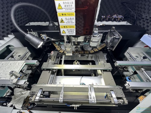
Steckverbinder, Relais, Transformatoren, Trimmer, Elkos, DIP-ICs und Flachstecker – die Teile, die in Töpfen, Stangen und Trays ankommen und noch von Hand gesetzt werden. Der S7900 nimmt sie mit einer Vakuumpipette oder einem Luftgreifer auf, prüft Polarität und Anschlusszustand mit einer Unterseitenkamera, bestückt in jedem Winkel von 0 bis 360 Grad und biegt die Anschlüsse in einem von vier Mustern um, damit nichts in die Welle aufschwimmt.
Wichtigste Merkmale
Manuelle Bestückung wächst nicht mit dem Auftragsbuch
Das Kundenlösungsdokument hinter dieser Seite beginnt mit derselben Liste, die jedes EMS-Werk kennt: jährlich steigende Lohnkosten, ein schrumpfender Pool an Hilfskräften, Fachkräfte mit langer Einarbeitungszeit, schichtabhängig schwankende Qualität, Kapazität, die sich nicht zusagen lässt, und Stellfläche, die von Arbeitstischen belegt wird. Nichts davon sind Bestückfehler. Es sind die Kosten eines manuellen Prozesses…
Odd-Form-Verpackungen sind von Natur aus uneinheitlich
Eine einzige Odd-Form-Stückliste mischt fünf Liefergebinde – loses Schüttgut, Ammo-Pack, Gurt, Tray und Stange –, weil die Bauteilhersteller so liefern. Eine Maschine, die nur Gurt verarbeitet, ist keine Odd-Form-Maschine. Die Plattform S7900 ist mit allen vier Feederfamilien auf einem Grundgestell dokumentiert: Wendelförderer für Schüttgut, Gurt für gegurtete Teile, Stange für Relais und ICs und Tray für Steckverbinder und Transformatoren, mit einem…
Aufschwimmende Teile sind ein Wellenlötfehler, kein Bestückfehler
Ein bestücktes, aber nicht gesichertes Teil kann sich beim Wellenlöten anheben, und der Fehler zeigt sich nachgelagert als Brücke, Lunker oder Unterbrechung. Der S7900 begegnet dem am Bestückkopf: Eine optionale Unterseiten-Umbiegeeinheit biegt die Anschlüsse nach dem Einsetzen um, sodass sich das Teil nicht bewegen kann. Vier Biegemuster sind dokumentiert – nach außen, nach innen, kreisförmig und zwei Windungen –, und die Spezifikation nennt den Anschlussdurchmesser…
Spezifikationen
Werte wie in den Unterlagen von Southern Machinery veröffentlicht. Widersprechen sich zwei Quellen, werden beide Werte mit Quelle gezeigt.
| Size (L × W × H) | 1050 × 1680 × 1870 mm · 1300 × 1700 × 2000 mm · 1550 × 1900 × 2100 mm · 1300 × 1700 × 2000 mm · 1550 × 1900 × 2100 mm |
|---|---|
| Weight | 1250 kg · 1650 kg · 1750 kg · 1730 kg · 1800 kg |
| Operation system | Windows |
| No. of door | Single side · Double side · Single side |
| Safety grating (door) | Standard configuration |
| Air supply | 0.5 – 0.65 MPa (ANR) |
| Max power | 4.5 kW · 5.4 kW · 6.6 kW · 5.2 kW · 6.3 kW |
| Run power | 2 kW · 3.3 kW · 3.5 kW · not stated in the catalog · 3.5 kW |
| No. of insertion heads | 2 · 4 · 4 · 6 · 6 |
| Max component size | φ50 (35 × 35) mm · φ30 (17 × 17) mm · φ50 (35 × 35) mm |
| Component height | ≤ 25 mm · ≤ 30 mm · ≤ 25 mm · ≤ 20 mm · ≤ 30 mm |
| Component feeding type | Nozzle / clamp |
| Speed per component | 0.8 s · 0.7 s · 2 s (with lead clinching) · 0.6 s · 0.6 s |
| Placement accuracy (CPK ≥ 1.0) | ± 0.06 mm · ± 0.06 mm · ± 0.05 mm · ± 0.06 mm · ± 0.05 mm |
| Insert power | ≤ 29.4 N · ≤ 98 N · ≤ 29.4 N · ≤ 29.4 N · ≤ 29.4 N |
| Insertion direction | 0 – 360° |
| Insertion component / object | Connector, switch, socket, transformer, coils, ports, capacitors, resistors, IC, etc. |
| PCB size (L × W) | 70 × 70 ~ 300 × 500 mm · 70 × 70 ~ 410 × 500 mm · 70 × 70 ~ 450 × 400 mm · 70 × 70 ~ 410 × 350 mm · 70 × 70 ~ 410 × 360 mm |
| Carrier size (L × W) | max 350 × 500 mm · max 500 × 500 mm · max 500 × 550 mm · max 410 × 350 mm · max 410 × 360 mm |
| PCB thickness | 0.6 – 2.0 mm |
| Conveyor space | 25 / 20 mm · 30 / 20 mm · 25 / 20 mm · 20 / 20 mm · 30 / 20 mm |
| Max PCB weight | 5 kg · 2 kg · 5 kg |
| PCB included side width | ≥ 5 mm |
| PCB fixed type | Servo / cylinder clamping |
| Conveyor type | Chain · Belt · Chain |
| PCB direction | R to L / L to R |
| Conveyor section | 3 |
| Conveyor adjusting | Auto |
| Conveyor height | 750 ± 20 mm · 900 ± 20 mm · not applicable |
| Lead clinching unit | not applicable · not applicable · standard · not applicable · option |
| SMEMA / MES connection | Standard configuration |
| Vision — mark CCD (top) | 1 |
| Vision — component CCD (bottom) | 2 · 4 · 4 · 2 · 6 |
| 201 radial tape feeder | 4 · 6 · 6 · 10 · 6 |
| 218 radial tape feeder | 4 · 6 · 6 · 10 · 6 |
| 207 radial tape 90° feeder | 4 · 6 · 6 · 10 · 6 |
| 259 radial tape feeder | 4 · 6 · 6 · 10 · 6 |
| 254 radial tape feeder | 6 · 12 · 12 · 20 · 12 |
| 202 axial tape feeder | 4 · 6 · 6 · 10 · 6 |
| 222 tube feeder | 6 · 12 · 12 · 20 · 12 |
3 weitere Zeilen anzeigen
| 203 tube feeder | 4 · 6 · 6 · 10 · 6 |
|---|---|
| 205 bowl feeder | 4 · 4 · 4 · 8 · 4 |
| Tray feeder | 1 · 1 · 1 · 2 · 1 |
Modelle, Vergleiche und offene Punkte
The same board, read by packaging instead of by function (5 Zeilen)
| Supply format | Lines | Feeder family that handles it | Documented feeder figures |
|---|---|---|---|
| Loose bulk | 17 | Bowl feeder | 4 per machine on S7900-II / IV / VI-P, 8 on S7900-VI |
| Ammo pack (axial tape) | 9 | Axial tape feeder | 4 to 10 stations depending on model |
| Tape | 5 | Radial tape feeder, six widths | 4 to 20 stations per width |
| Tray | 3 | Tray feeder, single or automatic | 1 on S7900-II / IV / VI-P, 2 on S7900-VI |
| Tube | 2 | Tube feeder, two widths | 4 to 20 stations depending on model |
The same board, read by packaging instead of by function (36 Zeilen)
| Line | Component description as received | Reference | Supply format | Proposed machine |
|---|---|---|---|---|
| 01 | CAP ALUM 68µF 20% 250V RADIAL | C9 | Tape | Odd-form inserter |
| 02 | CAP CER 3300pF 1kV 10% RADIAL | C45 | Tape | Odd-form inserter |
| 03 | CAP CER 2200pF 440VAC 20% RADIAL | C46 | Tape | Odd-form inserter |
| 04 | CAP ALUM 330µF 20% 25V RADIAL | C47 | Bulk | Odd-form inserter |
| 05 | CAP ALUM 2200µF 20% 25V RADIAL | C48 | Bulk | Odd-form inserter |
| 06 | CAP ALUM 10µF 20% 25V RADIAL | C50 | Tape | Odd-form inserter |
| 07 | Noise suppression cap 0.22µF 275Vac 10% P=15.0mm | C63 | Bulk | Odd-form inserter |
| 08 | Noise suppression cap 0.01µF 275Vac 10% P=10.0mm | C98 | Bulk | Odd-form inserter |
| 09 | Connector P=2.5mm 2-pin 1-row vertical unshrouded | J12 J18 | Bulk | Odd-form inserter |
| 10 | Connector P=2.5mm 4-pin 1-row right-angle unshrouded | J3 | Bulk | Odd-form inserter |
| 11 | Connector P=2.5mm 5-pin 1-row right-angle unshrouded | J6 | Bulk | Odd-form inserter |
| 12 | Connector P=2.5mm 4-pin 1-row vertical unshrouded | J8 | Bulk | Odd-form inserter |
| 13 | Spade terminal | J15 J20 | Bulk | Odd-form inserter |
| 14 | Connector P=2.5mm 2-pin 1-row right-angle hook, ivory | J19 | Bulk | Odd-form inserter |
| 15 | Connector P=2.0mm 34-pin 2-row right-angle latch type | J22 | Tray | Odd-form inserter |
| 16 | Connector P=2.0mm 5-pin 1-row vertical white | J27 | Bulk | Odd-form inserter |
| 17 | Relay 12Vdc SPDT 16A flux protection | K2 | Tube | Odd-form inserter |
| 18 | Varistor 212V 2.5kA disc 10mm | MOV1 | Tape | Odd-form inserter |
| 19 | Sensing gauge | PS1 | Tray | Odd-form inserter |
| 20 | Transformer | T1 | Tray | Odd-form inserter |
| 21 | IC off-line switch PWM, 8-pin DIP | U6 | Tube | Odd-form inserter |
| 22 | Trimmer potentiometer 500Ω 30% 0.1W | VR1 | Bulk | Odd-form inserter |
| 23 | Trimmer potentiometer 100Ω 30% 0.1W | VR2 | Bulk | Odd-form inserter |
| 24 | 2.5mm vertical header, 2-pin | J7 | Bulk | Odd-form inserter |
| 25 | 2.5mm vertical header, 4-pin | J11 | Bulk | Odd-form inserter |
| 26 | Connector P=2.5mm 2-pin 1-row right-angle shrouded | J2 | Bulk | Odd-form inserter |
| 27 | DIODE GEN PURP 400V 1A DO-204AL | D1 D2 D3 | Ammo | Axial inserter |
| 28 | DIODE SCHOTTKY 80V 5A DO-201AD | D10 | Ammo | Axial inserter |
| 29 | DIODE GEN PURP 1kV 1A DO-41 | D11 | Ammo | Axial inserter |
| 30 | TVS diode, axial | D72 | Ammo | Axial inserter |
| 31 | RES AXIAL 100Ω 5% 1/4W | R21 | Ammo | Axial inserter |
| 32 | RES RADIAL 2Ω 5% 3W | R26 | Ammo | Axial inserter |
| 33 | RES 0.0Ω 3A jump, axial | R27 | Ammo | Axial inserter |
| 34 | (no description in the source file) | R55 | Ammo | Axial inserter |
| 35 | RES AXIAL 100kΩ 5% 1W | R72 | Ammo | Axial inserter |
| 36 | HARNESS, GROUND CRIMP, PCBA | AC(G) | Bulk | Manual — not a feeder component |
Where the documents disagree — printed side by side, not averaged (15 Zeilen)
| Item | Customer solution document | S7900 catalog 2025 | Precision S7900 presentation |
|---|---|---|---|
| No. of insertion heads | 6 heads (3 + 3 layout) | 2 / 4 / 4 / 6 / 6 — one value per model | not stated in the catalog |
| Speed | 2,400 CPH (conditional) | 0.6 – 0.8 s per component | 4,700 CPH max |
| Placement accuracy | 0 – 360°, ± 0.1° adjustable (orientation only) | ± 0.05 / ± 0.06 mm, CPK ≥ 1.0 | ± 0.06 mm |
| Max PCB size | L490 × W420 mm | 70 × 70 ~ 450 × 400 mm (largest model) | 480 × 390 mm |
| Min PCB size | L50 × W50 mm on one page, L60 × W60 mm on another — the document disagrees with itself | 70 × 70 mm | not stated in the catalog |
| Machine size (L × W × H) | W1670 × D1620 × H1690 mm | 1050 × 1680 × 1870 mm to 1550 × 1900 × 2100 mm | not stated in the catalog |
| Machine weight | approx. 1300 kg | 1250 – 1800 kg depending on model | not stated in the catalog |
| Max PCB weight | 3 kg | 5 kg on II / IV / VI-P, 2 kg on VI | not stated in the catalog |
| Conveyor height | 930 ± 30 mm | 750 ± 20 mm on II / IV, 900 ± 20 mm on IV-P | not stated in the catalog |
| Power | Single phase AC 200 – 220 V, 50/60 Hz, 2 kW | Max 4.5 – 6.6 kW; run 2 – 3.5 kW | Single phase 220 VAC, 50/60 Hz |
| PCB thickness | not stated in the catalog | 0.6 – 2.0 mm | 0.76 – 2.36 mm |
| Max component size | L5 × W5 × H6 to L40 × W40 × H45 mm, height including the lead | φ30 (17 × 17) to φ50 (35 × 35) mm, height ≤ 20 to ≤ 30 mm | not stated in the catalog |
| Vision cameras | 4 CCD — 2 upper + 2 bottom | 1 mark CCD (top) + 2 / 4 / 4 / 2 / 6 component CCD (bottom) | not stated in the catalog |
| Feeder stations | 6 stations, expandable to 48 feeders | Per-model maxima in the table above | not stated in the catalog |
| Lead clinching unit | not stated in the catalog | Standard on IV-P, option on VI-P, unavailable on II / IV / VI | Described as an optional automatic unit with four lead-bending types |
What one machine produced on the project it was specified for (1 Zeilen)
| Case | Machines | Tact time | Cavities | Insertions per machine (varieties / pieces) | Cycle time | Output |
|---|---|---|---|---|---|---|
| PCBA #2 | 1 set | ≤ 1.6 s | 2 | 1st machine 1 / 4 · 2nd machine 1 / 4 · 3rd and 4th not used | ≈ 11 s | ≈ 650 pcs/hr |
Im Detail
The awkward parts are the ones still sitting on the bench
A modern line places chips at SMT speed and radial parts at radial speed. What is left over is the odd-form band: connectors, relays, transformers, trimmers, bulk electrolytics, DIP ICs and spade terminals. They arrive in five different packagings, several of them have leads that bend or polarity that matters, and they are exactly the parts a manual station gets wrong at the end of a shift. This page starts from a real customer BOM — thirty-six through-hole lines — so you can see how much of…
- Manual insertion does not scale with the order book. The customer solution document behind this page opens with the same list every EMS plant recognises: labour cost rising year on year, a shrinking general labour pool, skilled operators who take time to train, quality that drifts with the shift, capacity that cannot be promised, and floor space consumed by benches. None of those are insertion defects. They are the cost of running a manual process…
- Odd-form packaging is inconsistent by design. A single odd-form BOM mixes five supply formats — loose bulk, ammo pack, tape, tray and tube — because that is how the component makers ship. A machine that only takes tape is not an odd-form machine. The S7900 platform is documented with all four feeder families on one base: bowl for bulk, tape for taped parts, tube for relays and ICs, and tray for connectors and transformers, with a…
- Floating parts are a wave-soldering defect, not an insertion defect. A part that is inserted but not secured can lift during wave soldering, and the fault shows up downstream as a bridge, a void or an open. The S7900 addresses it at the insertion head: an optional bottom clinching unit bends the leads after insertion so the part cannot move. Four bend patterns are documented — outward, inner, circular and two turns — and the specification gives lead diameter…
Thirty-six lines from a real THT board, split by which machine should place them
This is the part of an odd-form project that decides the price. Before anyone quotes a machine, someone has to read the bill of materials and answer one question per line: does this go on the odd-form inserter, on an axial inserter, or does it stay manual? The analysis below was done line by line on a customer board — thirty-six through-hole lines — and it is reproduced here because the split, not the machine specification, is what tells you whether the project is worth doing.
- Lines for the odd-form inserter. Electrolytic and ceramic capacitors, noise-suppression capacitors, seven connectors, a spade terminal, a relay, a varistor, a sensing gauge, a transformer, a DIP IC and two trimmer potentiometers. These are the parts with body shapes, polarity and lead pitches that a tape-fed radial machine cannot take.
- Lines for the axial inserter. Four diodes and five resistors, all supplied in ammo pack on axial tape with a fixed lead span. Sending these to an odd-form head would waste its flexibility; they belong on an axial machine running at its own cycle rate, which is why the same solution document proposes the two machines together.
- Line that stays manual. A crimped ground harness. It is not a component on a feeder — it is a wire assembly that is routed and terminated by hand, and no insertion machine in this class addresses it. Being explicit about the one line you cannot automate is what makes the other thirty-five credible.
- The same board, read by packaging instead of by function. Feeder count is bought per packaging format, not per component type. Read this way, the same thirty-six lines tell you how many bowl, tape, tube and tray stations the machine needs before anyone has quoted a price. Verified material Component descriptions, supply formats and line count are taken directly from the customer component analysis supplied to Southern Machinery. Part numbers, reference…
From a bowl of loose parts to a clinched lead in six stages
The sequence below follows the machine's own description of its mechanism, taken from the customer solution document and the S7900 catalog. Each stage names the subassembly that performs it, because when a line stops you need to know which of them to look at.
Where the documents disagree — printed side by side, not averaged
Three documents describe this machine: the customer solution document that specified it, the 2025 product catalog, and a precision automation presentation. They do not agree. A page that quietly picked one figure per row would look tidier and would be wrong, so every disagreement is printed here with both values and the document each came from. None of these are averaged, and none are resolved by Southern Machinery on your behalf — the machine you buy is the machine in the contract, so the…
Four feeder families on one base — because odd-form parts arrive five different ways
Feeder choice is decided by the BOM analysis, not by preference. On the thirty-six-line board above, seventeen lines arrive loose in bulk, nine on axial ammo pack, five on tape, three on trays and two in tubes. That is a five-format problem, and it is the reason a tape-only machine cannot be called an odd-form machine. Figures below are from the S7900 catalog's feeder pages.
- Loose bulk, oriented by track and vibration. For components that ship loose: connectors, terminals, capacitors, LEDs, crystals, ICs. The bowl orients each part mechanically and the pickup point presents it to the head. The customer solution document describes a patented bowl control unit that drives up to twelve vibration sources from hardware and software in one unit, and notes that the vibration supply is DC rather than mains so the…
- Radial and axial tape, six widths plus 90° bending. The catalog lists five radial tape feeder widths — 201, 218, 207 with a 90° bend, 259 and 254 — plus a 202 axial tape feeder. The standard tape feeder is described as motor-driven with a maximum pitch of 22.5 mm and a 90° bent-lead function, accepting tape material from 0.4 to 0.8 mm, with a stated feed rate of 1.1 to 1.5 s per component and a separate electric feed figure of 0.8 to 1.0 s per…
- Relays, DIP ICs and anything shipped in a stick. Two tube feeder types are listed, 222 and 203. The catalog gives a feed rate of 0.8 to 1.5 s per component, compatibility with all brands of mounting and insertion machine, a tube size customisable up to 50 × 50 × 50 mm, and a component adaptation example of relays within 30 × 22 × 40 mm. Load capacity is quoted as up to 4 kg in one place and up to 2 kg in another on the same catalog page — both…
- Connectors, transformers and large bodies on a blister tray. The tray feeder takes components supplied on blister trays — the solution document names USB and HDMI sockets and transformers, the catalog names resistors, capacitors, diodes, small connectors, small ICs, transistors and precision resistors. The catalog quotes a structure rated for 200 kg, a drive of 0.4 MPa at 100 W in one place and AC 220 V at 2000 W with 0.5 to 0.8 MPa in another, a touch…
- Grippers and nozzles are made in the same factory. Southern Machinery designs and manufactures the pickup tooling as well as the machine. The catalog devotes two pages to customised grippers and nozzles, and the head mount is a standard fast-joint system so tools can be exchanged between spindles. That matters when a component has no flat face for a vacuum nozzle, or when a body is too delicate for a gripper — the tool is a design task rather…
What one machine produced on the project it was specified for
A rated tact speed tells you how fast a head can move. It does not tell you how many boards an hour leave the machine. The customer solution document includes the case table below, and it is the most useful figure on this page because it is the only one measured on a real board rather than on a bare head.
- Two cavities, not one board at a time. The case runs two boards per cycle, which is what turns an 11-second cycle into roughly 650 boards an hour. Cavity count is a fixture and program decision, not a machine specification, and it is usually the single largest lever on real output — larger than any difference between two models in the same family.
- Four insertions per board. The board in the case needs four odd-form insertions, supplied as one variety of four pieces per machine. At a tact time of 1.6 seconds or better, four insertions fit inside the 11-second cycle with time left for indexing and vision. Boards with more odd-form lines take longer, which is exactly why the rated tact figure should never be quoted as a board rate.
- Rated tact and case output are different numbers. The same document quotes a rated tact speed of 2,400 CPH and a case output of about 650 pcs/hr. Both are correct and they are not comparable. Before you build a business case, decide which one you are using, and ask for the case figure for your board — it is the one your finance team will recognise.
What happens after the machine lands
Southern Machinery has been designing and building auto insertion equipment since 2011 and has shipped more than fifty automatic insertion machines into Brazil, India, Malaysia, Indonesia, Thailand, Turkey, Saudi Arabia, Ecuador, Colombia and Argentina. The support model below is the one that kept those machines running.
Videos
Clips aus dem YouTube-Kanal von Southern Machinery. Von YouTube wird erst etwas geladen, wenn Sie auf Abspielen drücken.
Kataloge und Dokumente
- PDFS7900 Odd Form Machine Catalog 2025 — five models, full specification tableS7900 machine documents
- PDFS7900 THT odd form insertion machine — product sheetS7900 machine documents
- PDFPrecision S7900 odd form insertion machine — presentationS7900 machine documents
- PDFS7900 odd form machine operation manualS7900 machine documents
- PDFS7000 Odd Form Insertion Machine manual 2024 — earlier platform in the same familyS7900 machine documents
- PDFS7020T terminal insertion machine — user manualS7900 machine documents
- 3DS3000 radial + S7900 odd form insertion machine with PCB loading and magazine3D drawings and line layouts
- 3DS7020T reel terminal insertion machine, 3D view3D drawings and line layouts
- 3DS3010A radial + S7020T bowl terminal insertion machine with magazine loader3D drawings and line layouts
- PDFS7000 odd-form with radial, axial and tube feeders — feeder layout drawing3D drawings and line layouts
- XLSXTHT insertion ROI calculatorWorksheets and project tools
- XLSXTHT auto insertion ROI worksheetWorksheets and project tools
- XLSXTHT staffing audit calculatorWorksheets and project tools
- XLSXTHT staffing audit worksheetWorksheets and project tools
- PDFROI calculator template, printedWorksheets and project tools
- PDFSouthern Machinery odd-form insertion solution — family overviewWorksheets and project tools
- LINKFull resource library
- 3DProduct catalogue board
Technische Notizen
ARTICLE 01The Parts That Keep a Bench Staffed Are the Ones Nobody Sizes a Machine For
An SMT line and a radial inserter take the easy part of a through-hole board. What is left over is small in count, awkward in shape, and expensive enough to keep four people at a bench. Full articles are in English. The summary above carries the argument in your language. Walk a through-hole department at the end of…
ARTICLE 02Twenty-Six Lines Here and Nine Lines There — How a Through-Hole BOM Actually Splits
The decision that sets the price of an odd-form project is not which machine to buy. It is which lines go on which machine, and that decision is made before any quotation exists. Full articles are in English. The summary above carries the argument in your language. The scene: a quotation arrives for an odd-form…
ARTICLE 03Bowl, Tube, Tray and Tape — Why Odd-Form Feeders Are Counted by Packaging
Feeder stations are bought per supply format, not per component type. Read the same BOM the second way and the machine's price stops being a mystery. Full articles are in English. The summary above carries the argument in your language. Here is the meeting that goes wrong. Engineering lists fourteen odd-form…
ARTICLE 04A Part That Is Inserted but Not Clinched Will Float Into the Wave
Floating components are diagnosed as a wave-soldering problem. The cause is at the insertion stage, and it has four documented remedies. Full articles are in English. The summary above carries the argument in your language. A board comes off the wave with a bridge under a connector, or a void where a transformer…
ARTICLE 05Two Thousand Four Hundred Components an Hour Comes With Conditions Attached
Three source documents describe the same machine family at three different speeds. None of them is wrong. Reading them together is the skill. Full articles are in English. The summary above carries the argument in your language. Every insertion machine is sold on a rate, and every production manager has watched a…
ARTICLE 06Inserting at Any Angle Changes the Layout Before It Changes the Machine
A 0-and-90-degree insertion limit is paid for in board area and jumper wires long before it is paid for at the machine. Full articles are in English. The summary above carries the argument in your language. Look at a through-hole layout drawn by someone who has spent years working with a machine that inserts at two…
Vollständige Artikel auf der interaktiven Produktseite lesen →
Häufige Fragen
Wie hoch ist die reale Bestückgeschwindigkeit des S7900?
Es sind drei Werte veröffentlicht, die Unterschiedliches messen. Der Katalog 2025 nennt die Zeit pro Bauteil je Modell: 0,8 s beim Zwei-Kopf-Modell S7900-II, 0,7 s beim Vier-Kopf-Modell S7900-IV, 2 s beim Vier-Kopf-Modell S7900-IV-P mit Umbiegen und 0,6 s bei beiden Sechs-Kopf-Modellen. Das Kundenlösungsdokument nennt 2.400 Bauteile pro Stunde unter bestimmten Bedingungen. Die Präsentation Precision S7900 nennt maximal 4.700 Bauteile pro Stunde. Der Katalog druckt außerdem einen Praxisfall mit rund 11 s Zykluszeit und rund 650 Stück pro Stunde. Planen Sie mit dem Wert pro Bauteil, betrachten Sie das Maximum als Obergrenze und lassen Sie Ihre eigene Platine messen.
Welche Bauteile kann er bestücken?
Odd-Form-Bauteile in einem weiten Gehäusebereich: Steckverbinder, Relais, Transformatoren, Trimmer, Elkos, Entstörkondensatoren, Varistoren, Flachstecker, DIP-ICs und LEDs in Sonderform. Die maximale Bauteilgröße ist je Modell von 17 × 17 mm bis 50 × 50 mm dokumentiert, die zulässige Höhe von 20 mm bis 30 mm. Die Aufnahme erfolgt per Vakuumpipette oder Luftgreifer, beides lässt sich im selben Kopfsatz kombinieren.
Wie viele Modelle gibt es, und welches brauche ich?
Fünf: S7900-II, S7900-IV, S7900-IV-P, S7900-VI und S7900-VI-P mit 2, 4, 4, 6 und 6 Köpfen. Der IV-P hat das Umbiegen serienmäßig und mit 2 s die längste Zeit pro Bauteil. VI und VI-P haben die meisten Feederstationen und die geringste Bestückkraft. Der II ist mit 1250 kg das kleinste Gestell. Welches passt, hängt von Ihrer Bauteilzahl, Ihrer Platinengröße und davon ab, ob Sie Umbiegen benötigen – senden Sie uns die Teileliste, und wir sagen es Ihnen.
Brauche ich trotzdem noch einen separaten Axialbestücker?
Meist ja, und bei der auf dieser Seite analysierten Platine eindeutig. Neun von sechsunddreißig THT-Positionen waren axiale Ammo-Pack-Teile mit festem Rastermaß – vier Dioden und fünf Widerstände. Diese an einen Odd-Form-Kopf zu geben, verschwendet seine Flexibilität an Teile, die eine schnellere Spezialmaschine besser verarbeitet. Das Kundenlösungsdokument hinter dieser Seite schlägt genau deshalb beide Maschinen zusammen vor.
Was ist Umbiegen, und brauche ich es?
Eine Einheit auf der Unterseite, die die überstehenden Anschlüsse nach dem Einsetzen umbiegt, damit sich das Bauteil beim Wellenlöten nicht bewegt. Ohne sie kann sich ein eingesetztes, aber nicht gesichertes Teil anheben und eine Brücke, einen Lunker oder eine Unterbrechung verursachen. Der Katalog dokumentiert vier Biegemuster – nach außen, nach innen, kreisförmig und zwei Windungen – und als Biegespezifikation einen Anschlussdurchmesser unter 1,0 mm bei mindestens 2 mm freiem Anschluss, vorbehaltlich der endgültigen Konstruktion. Umbiegen ist bei einem Modell der Familie serienmäßig und bei einem anderen optional; prüfen Sie es anhand Ihrer Konfiguration.
Wie viele Feederstationen brauche ich?
Zählen Sie Ihre Stückliste nach Liefergebinde, nicht nach Bauteiltyp. Feederstationen werden je Verpackungsfamilie gekauft – Wendelförderer für loses Schüttgut, Gurt für gegurtete Teile, Stange für Relais und DIP-ICs, Tray für Steckverbinder und Transformatoren. Der Katalog dokumentiert die Stationszahlen je Familie und Modell und weist darauf hin, dass bei gemischten Feedertypen die Anzahl von der Kombination abhängt, Stationen sich also nicht einfach addieren. Fordern Sie eine Zeichnung der Stationsbelegung statt einer Gesamtzahl an.
Kann er in anderen Winkeln als 0 und 90 Grad bestücken?
Ja. Die Bestückrichtung ist über 0 bis 360 Grad dokumentiert, das Kundenlösungsdokument nennt eine Einstellauflösung von ±0,1 Grad. Der Winkel ist ein Programmfeld pro Zeile statt einer Vorrichtung – so kann ein Layout einen Steckverbinder oder Transformator in seiner natürlichen Ausrichtung platzieren, statt ihn rechtwinklig zu drehen und Drahtbrücken zur Umgehung hinzuzufügen.
Welche Platinengrößen verarbeitet er?
Der Katalog 2025 nennt für jedes Modell ein Minimum von 70 × 70 mm und ein Maximum von 300 × 500 mm beim S7900-II bis 450 × 400 mm beim S7900-IV-P. Die Platinendicke ist mit 0,6 bis 2,0 mm dokumentiert, das maximale Platinengewicht mit 5 kg bei vier Modellen und 2 kg bei einem, und der Katalog verlangt einen Platinenrand von mindestens 5 mm, damit das Transportband greifen kann. Das Kundenlösungsdokument nennt für das Linienband andere Werte; beide stehen in der Offenlegungstabelle oben.
Warum haben manche Werte auf dieser Seite zwei oder drei Angaben?
Weil drei Dokumente diese Plattform beschreiben und für unterschiedliche Zwecke geschrieben wurden. Das Kundenlösungsdokument beschreibt eine vorgeschlagene Konfiguration; der Katalog 2025 die ganze Fünf-Modell-Familie; die Precision-Präsentation die Plattform allgemein. Wo sie für denselben Umfang unterschiedliche Werte nennen, werden beide mit Dokumentangabe gedruckt und keiner gemittelt. Die Offenlegungstabelle weiter oben auf dieser Seite listet jeden Widerspruch auf.
Ist er bereit für MES und Industrie 4.0?
Die Steuerungsplattform läuft mit einer lizenzierten Microsoft-Windows-Oberfläche auf Chinesisch und Englisch, und die OCM-Version unterstützt die Offline-Programmierung aus CAD- oder TXT-Dateien. Der Katalog nennt Offline-Programmierung und Datenaustausch unter den Vorteilen der Plattform. Legen Sie vor der Installation fest, wofür die Produktionsdaten genutzt werden sollen – ein OEE-Dashboard, einen Wartungsplan oder einen Leistungsbericht für das Controlling –, denn eine Maschine, die Daten liefert, deren Nutzung niemand vereinbart hat, ist eine Maschine mit ungenutzter Funktion.
Was beinhaltet die kostenlose Vorführung?
Southern Machinery führt eine kostenlose Vorführproduktion mit unbestückten Platinen durch, die Sie liefern, überträgt den Maschinenlauf live, damit Sie selbst zusehen können, statt uns beim Wort zu nehmen, und erstellt anschließend einen schriftlichen Bewertungsbericht. Senden Sie die Platinen, die Odd-Form-Teileliste mit Liefergebinden und das Monatsvolumen; der Bericht kommt mit dem gemessenen Ergebnis und der Aufteilung zwischen maschineller und manueller Bestückung zurück.
Was sollte ich mit einer Anfrage senden?
Vier Dinge: die THT-Stückliste mit dem Liefergebinde jeder Position, die Odd-Form-Teileliste mit Anschlussdurchmessern und Lochgrößen, Abmessungen und Dicke der Platine sowie das monatliche Platinenvolumen. Mit diesen vier Angaben liefern wir die Dreiteilung zwischen Odd-Form, axial und manuell, legen die Feederbank nach Verpackungsfamilie aus, empfehlen ein Umbiegemuster je Teil und nennen Ihnen eine Bestückzeit für Ihre Platine statt einer Maschinenspezifikation.
Ähnliche Produkte

THT-Bestück- und Wellenlötlinie für Handy-Ladegeräte – smarte EMS-Leiterplattenbestückung
Schlüsselfertige THT-Linie für Leiterplatten von Handy-Ladegeräten und Netzteilen: Platinenlader, Radialbestücker S3010A, Terminal- und Odd-Form-Bestücker S7020, Vier-Kopf-Odd-Form-Zelle mit Wendel- und Schüttgutfeedern, Wellenlötanlage S-WS350 und Auslauf. Interaktive 3D-Linie, Spezifikationen mit Quellen, Videos, Kataloge und Amortisationsrechnung.
Radialbestückautomat S3000 für die smarte EMS-THT-Leiterplattenbestückung
Radialbestückautomat S3000 für die THT-Leiterplattenbestückung: gegurtete Radialbauteile mit bis zu 20.000 CPH, Bestückwinkel 0–360 Grad, 10 Feederstationen und Lochkorrektur per Bildverarbeitung.

Axialbestückautomat S4000 für die smarte EMS-THT-Leiterplattenbestückung
Axialbestücker S4000: veröffentlichte Höchstgeschwindigkeit 20.000 CPH, 5–60 modulare Feederstationen, Bestückung in jedem Winkel auf einem Servo-Drehtisch, doppelte Drahtbrücken-Feeder, Platinendicke 0,79–2,36 mm, Platinen 50 x 50 bis 400 x 300 mm. Servoangetrieben, EtherCAT, MES-fähig.

S-300B Radial-Biege- und Gurtmaschine
Radial-Biege- und Gurtmaschine S-300B: formt das Anschlussraster, prüft Polarität und Wert und gurtet dann 180 ± 20 Bauteile pro Minute, in Box oder auf Rolle.
Einige technische Angaben auf dieser Seite (Tabellen, Dokumenttitel) erscheinen wie veröffentlicht auf Englisch.
Angebot anfordern: S7900 Odd-Form-Bestückautomat – Lösung für die smarte EMS-THT-Leiterplattenbestückung
Senden Sie Ihre Platine, Bauteilliste oder Ihr Maschinenmodell, und wir antworten mit einer Konfiguration und einem Angebot. Preise werden projektbezogen kalkuliert.