
S-300B Radial Lead Molding and Taping Machine
Radial leads moulded, tested and taped before the inserter ever asks for them
S-300B radial lead molding and taping machine: forms the lead pitch, tests polarity and value, then tapes 180 plus or minus 20 components a minute, boxed or reeled.
The S-300B takes loose radial components out of a bulk bowl, forms them to the lead pitch your inserter is set for, checks polarity and electrical value, ejects what fails, and delivers a sealed taped pack - boxed or reeled - at 180 ± 20 components a minute. One machine between the bin and the feeder.
Key features
Taping is the step nobody costed
Ask for the cycle time of a THT line and you will get insertion, wave soldering and test. Ask for the time it takes to hand-form and hand-tape radial parts and the room goes quiet. It is usually the only station where the output of the whole line is set by how many people you can stand next to a bench.
A polarity error that never reaches the tester
Insert a radial electrolytic capacitor the wrong way round and it will pass a simple continuity check. It fails weeks later, in the field, with the case split. Sorting polarity by eye on a bench puts that failure into your warranty numbers instead of your scrap bin.
Every reel you buy is a tape you did not control
Pre-taped components are convenient right up to the moment your inserter starts mis-picking, and then the argument is between your line and a supplier you cannot audit. Taping in-house moves the tape specification - pitch, hole diameter, taping height, polarity direction - inside your own process, where you can change it.
Specifications
Figures as published in Southern Machinery documents. Where two sources disagree, both values are shown with their source.
| Model code | S-300B Fully Automatic High-Speed Molding and Taping Machine · S-300B Automatic Molding and Taping Machine · S300B radial (LED) lead components taping machine · DT-300BSTD 全自动成型编带机 - supplier model, same machine class |
|---|---|
| Machine function | Automatic lead forming (moulding) and taping of radial lead components, with testing and sorting · Fully automatic high-speed moulding and taping of radial components, testing and sorting good from defective · Radial and LED lead forming and taping · Automatic forming and taping of radial lead components |
| Control system | Single-chip microcomputer as the core control unit · The world's most stable brand PLC, or a single-chip control system · Not stated · Single-chip control system |
| Operator interface | Liquid-crystal display for order placement, simulating the status of each control point · Touch-screen operation interface · Touch screen visible in the walkthrough · Touch screen with alarm display and parameter pages |
| Taping speed | 180 ± 20 PCS/minute · 180 ± 20 pieces per minute; speaker notes also quote up to 200 pieces per minute · Not stated · 120 - 180 PCS/minute normal operating speed |
| Component diameter - standard | Ф6 - Ф10 mm · Ф6 - Ф10 mm standard fixture configuration · Not stated · Ф3 - Ф10 mm |
| Component diameter - fixture sets | Ф4 - Ф6 share one set of fixtures, Ф8 - Ф10 share another; conventional range Ф4 - Ф10 · Two fixture sets, one for Ф4-Ф6 and one for Ф8-Ф10; other sizes within Ф4-Ф10 to order · Not stated · Not stated |
| Component length | L = 5 - 30 mm · 5 mm to 30 mm · Not stated · 5 - 30 mm |
| Formed lead pitch - standard | 2.5 mm, 3.5 mm, 5.0 mm · 2.5 mm, 3.5 mm, 5.0 mm · 2.5 mm lead shown being formed, 5.0 mm die described · 2.0 mm, 2.5 mm, 3.5 mm, 5.0 mm |
| Formed lead pitch - to order | 7.5 mm, 10 mm, 15 mm and above, ordered separately · 7.5 mm, 10 mm and 15 mm custom pitches can be ordered · Not stated · 7.5 mm and above optional |
| Tape hole pitch | 12.7 mm standard; other hole pitches customised on request · 12.7 mm standard · Not stated · 12.7 mm, with 15 mm optional |
| Tape hole diameter | 4.1 mm · 4.1 mm · Not stated · Ф4 mm with a tolerance of plus 0.2 mm |
| Taping height (hole centre to component base) | 17 mm - 21 mm · 17 mm - 21 mm · Not stated · 17 - 22 mm |
| Polarity selection | Not stated · Not stated · Positive lead or negative lead first, selectable; the machine re-orients the part to suit · Positive lead first or negative lead first, two selectable modes |
| Packaging method | Boxed or coiled · Boxed (ammo packing) and coiled (reel) packing methods both supported · Not stated · Boxed as standard, coiled optional |
| Paper tape | Not stated · Not stated · Not stated · 18 mm wide, 0.38 mm or 0.47 mm thick, selected to the product |
| Top tape width | Not stated · Not stated · Not stated · 6 mm, 10 mm, 12 mm or 15 mm, selected to the product |
| Lead trim | Not stated · Not stated · Leads beyond roughly 25 mm are trimmed at the cutting station before taping · A cutting station removes the excess where the lead is too long |
| Reject handling | Good and defective products sorted automatically when the tester is fitted · Defective products sorted out automatically · The eject gate opens for a good part and drops a failed part into a scrap tube · The eject gate closes for a good part and opens to reject a defective part |
| Drive system | Servo control system replacing the traditional clutch · Servo control system replacing the traditional clutch · Not stated · Servo control system replacing the traditional clutch |
| Cam accuracy | All cams imported, grinding accuracy 0.01 mm · Imported cams ground to 0.01 mm accuracy · Not stated · All cams imported, grinding accuracy 0.01 mm |
| Frame | Square rack feeder, precision fixtures of special materials on an accurate centre line · Not stated · Aluminium profile frame with branded panels visible in the walkthrough · Imported aluminium profile frame, corrosion resistant |
| Power supply | 220 V / 50 Hz / 1.6 kW · 220 V / 50 Hz / 1.6 kW · Not stated · 1 HP motor, 220/380 V, 50/60 Hz |
| Air pressure | 4 - 5 kg/cm² · 4 - 5 kg/cm² · Not stated · 4 - 5 kg/cm² |
| Machine dimensions (L × W × H) | 2200 × 1200 × 1500 mm · 2200 × 1200 × 1500 mm · Not stated · Not stated |
| Machine weight | 700 - 900 kg · 700 - 900 kg · Not stated · Not stated |
Models, comparisons and open points
Where the documents disagree (6 rows)
| Parameter | What the S-300B documents say | What the other source says | What the difference means | Status |
|---|---|---|---|---|
| Model naming | The product sheet and the presentation deck both call the machine S-300B. The walkthrough video calls it S300B, without the hyphen. | The image library also holds a machine photographed and labelled S-300BSTD, and the supplier manual supplied with the enquiry covers a DT-300BSTD. | Four codes circulate for what is presented as one machine class. S-300B is the code the product sheet and the deck agree on, so it is the code used on this page. If your quotation names S-300BSTD, ask which of the two it is - they are not the same build. | To be confirmed |
| Control system and operator interface | The product sheet describes a single-chip microcomputer as the core control unit, with a liquid-crystal display for order placement that simulates the status of each control point. | The presentation deck describes the world's most stable brand PLC or a single-chip control system, with a touch-screen operation interface. | One document describes a fixed LCD annunciator panel and the other a touch screen, and they do not describe the same hardware. The machine photographs show a colour touch panel. This matters at quotation time: a touch panel and an LCD annunciator are different spares, different training and different prices. | To be confirmed |
| Taping speed | The product sheet states a production capacity of 180 ± 20 PCS/minute, which is a band from 160 to 200. | The presentation deck repeats 180 ± 20 pieces per minute, and its speaker notes then say the machine processes up to 200 components per minute - the top of the band presented as the rate. The supplier manual for this class states 120 - 180 PCS/minute. | Three different framings of the same machine. The band is what the product sheet publishes and what this page quotes. Plan capacity from the bottom of the band, not the top, and treat 200 as a best case rather than a rate. | To be confirmed |
| Component diameter range | The product sheet gives the processed product diameter as Ф6 - Ф10 mm, and separately states that the machine handles a conventional range of Ф4 - Ф10 in which Ф4 - Ф6 share one set of fixtures. | The presentation deck says the standard fixture configuration covers Ф6 - Ф10 mm, with other sizes within the Ф4 - Ф10 range available as custom options. The supplier manual for this class states Ф3 - Ф10 mm. | The product sheet describes Ф4 - Ф6 as part of the conventional range with its own fixture set, while the deck describes that band as a custom option. If you run components below Ф6, confirm whether the Ф4 - Ф6 fixture set is a standard line item or an order - the answer changes both the lead time and the price. | To be confirmed |
| Taping height | The product sheet gives a taping height of 17 mm - 21 mm. | The presentation deck repeats 17 mm - 21 mm. The supplier manual for this class states 17 - 22 mm. | A 1 mm difference at the top of the range. Taping height is set against your inserter's pick height, so if your tape specification sits at 22 mm, ask for it in writing before the order rather than adjusting on site. | To be confirmed |
| Packaging and formed lead pitch | The product sheet lists boxed and coiled packaging as equal alternatives, and gives the standard formed lead pitch as 2.5 mm, 3.5 mm and 5.0 mm, with 7.5 mm, 10 mm and 15 mm and above ordered separately. | The presentation deck lists boxed (ammo packing) and coiled (reel) as both supported. The supplier manual for this class states boxed as standard with coiled optional, and prints an additional 2.0 mm pitch in the standard set. | Two questions to settle in the quotation rather than in the factory: whether coiled output is included or an option on the configuration you are buying, and whether 2.0 mm is a standard die or a special. Neither document is wrong; they describe different configurations. | To be confirmed |
What 180 components a minute is worth over a shift (3 rows)
| Taping speed | Components per hour | Components per 8-hour shift | Components per month, 26 days |
|---|---|---|---|
| 160 PCS/min (bottom of band) | 9,600 | 76,800 | 1,996,800 |
| 180 PCS/min (nominal) | 10,800 | 86,400 | 2,246,400 |
| 200 PCS/min (top of band) | 12,000 | 96,000 | 2,496,000 |
In detail
Nine stations between the bulk bin and the sealed tape
The station list below follows the machine walkthrough on the shop floor and the supplier manual for this machine class. It describes the order parts travel in, not the physical layout of the cabinet.
- Bulk feed. A vibratory bowl lifts loose components out of a bulk bin and orients them onto a linear track. A bowl eye stops the bowl when the track is full and a track eye slows the machine when the track runs short, so the machine tracks the feed rather than fighting it.
- Lead spread. A spreader opens the two leads apart before anything else touches the body. Doing this first is what keeps the die from closing on a crossed lead, and it is why the machine can run parts straight out of a bag with no pre-sorting.
- Lead forming. An integrated moulding die presses the leads to the formed pitch - 2.5 mm, 3.5 mm or 5.0 mm as standard. The die is one piece, so a pitch change is a die change, and the die comes off with four screws.
- Polarity test. The part is measured for polarity. For a radial electrolytic capacitor, an LED or a diode this is the difference between a board that works and a board that comes back, and it is checked before the part is committed to the tape.
- Re-orientation. If the polarity is the wrong way round for the tape the machine is building, a re-orientation station turns the part rather than rejecting it. Both directions are selectable, so the tape can be built positive-lead-first or negative-lead-first to match what your inserter expects.
- Value test. With the matching tester fitted, the machine reads capacitance and resistance and compares them with the window you set. This is the station that catches the mixed bag - a wrong value that would otherwise be taped, boxed and shipped as a good part.
- Lead trim. Over-long leads are cut to length before taping. Parts within the standard lead range pass through untouched; long-lead parts are trimmed at the station so the finished tape height is uniform instead of varying with the incoming lead length.
- Reject ejection. A gate holds open for a good part and drops a failed part into a chute. Rejects leave the machine through a tube into a scrap container, physically separated from the good stream, so a failed part cannot be re-introduced by a tired operator at the end of a shift.
Where the money goes inside the machine
Three things decide whether a taping machine is still running in year ten: what drives it, what the moving parts are made of, and whether you can still get the fixtures. All three are stated in the product sheet, and all three are visible in the machine photographs.
- Servo control instead of a clutch. The drive uses a servo control system in place of the traditional mechanical clutch. The clutch is the assembly that wears, slips and eventually seizes on this class of machine, and it is the single largest source of unplanned downtime. Removing it removes the failure mode, not just the symptom.
- Imported cams, ground to 0.01 mm. All cams are imported originals with a grinding accuracy of 0.01 mm. At 180 parts a minute the cam set is what determines whether the machine runs quietly or shakes itself apart: 0.01 mm is the difference between consistent lead forming and a die that closes a fraction early on every thousandth part.
- Special-material fixtures and an integrated die. The square-rack feeder, the precision fixtures and the moulding die are made of special materials on an accurate centre line. The die is integrated rather than assembled, so the forming dimensions stay true and the changeover is fast and does not damage the product. Two fixture sets cover Ф4-Ф6 and Ф8-Ф10.
Where the documents disagree
A specification table that quietly picks one of two numbers is worth less than one that shows both. Six parameters below do not agree across the supplied documents, or are stated in only one of them. Confirm each against the current drawing for your configuration before you order.
What 180 components a minute is worth over a shift
The published band is 180 ± 20 components per minute. The table converts that band into volume per hour, per shift and per month, so the number you plan with is a number you chose rather than one you were given.
What is configured, not just what is listed
A taping machine is only useful if the die, the fixtures and the tape all match the component you actually run. These are the items to settle with the order rather than after it.
- Moulding die for your formed pitch. 2.5 mm, 3.5 mm and 5.0 mm dies are standard. 7.5 mm, 10 mm, 15 mm and above are ordered separately. A die change is a four-screw operation, so a plant running two pitches can hold both.
- Second fixture set for the other diameter band. Ф4-Ф6 and Ф8-Ф10 each use their own fixture set. If your component mix spans both bands, order both sets with the machine instead of discovering the gap on the first changeover.
- Coiled output instead of boxed. Boxed (ammo pack) is the standard output. Coiled on a reel is the configuration to specify if your inserter takes reels - see the open points table, because the two supplied documents treat it differently.
- Capacitance and resistance tester. The testing and sorting function works when the matching tester is fitted. Without it the machine still forms and tapes; with it, the machine also rejects out-of-window parts before they reach the tape.
- Non-standard tape hole pitch. 12.7 mm is standard. Other hole pitches are customised on request, and 15 mm appears as an option in the supplier documentation for this class - confirm against your inserter's tape specification.
- Bowl and track tooling for your component. The bowl and the linear track are tooled to the component body. Send the drawing and a sample of the part, because a bowl that runs a 6 mm electrolytic will not necessarily run a square MKT of the same diameter.
Six steps from your component list to a validated tape
The order of work matters more than the speed of it. Most taping-machine problems that get blamed on the machine are a tape specification that was never agreed before the die was cut.
- Agree the tape specification. Before anything is built: lead pitch, polarity direction, taping height, hole pitch, paper width and thickness, top tape width, boxed or reeled. This single document decides the die, the fixtures and the consumables.
- Confirm the component. Send the component drawing and a physical sample. Body diameter, body height, lead diameter, lead length and body shape all move the fixture and the bowl tooling.
- Prepare the bench, power and air. 220 V single phase at 1.6 kW, 4-5 kg/cm² of clean dry air, and a level floor for a machine in the 700-900 kg band. Allow access on all four sides - the bowl, the reject tube and the output end all need to be reachable.
- Tune the bowl and the track. Bowl amplitude, track eye positions and the spreader are set against the real component, not against a drawing. This is the step where a bad sample shows up as a rate problem three weeks later.
- Validate the first tape. Run a full tape, then measure it: pitch, taping height, polarity direction, hole positions, and pull the sample against the component drawing. Keep the measured tape as the reference for the life of the machine.
- Hand over with a maintenance card. Operator training on the touch panel, the parameter pages and the alarm list, plus a written maintenance card with the lubrication points and the cam and eye inspection intervals for your own records.
What happens after the machine lands
A taping machine is a tooling project as much as a machine purchase. These are the four parts of the service that decide whether it stays running.
Videos
Clips from the Southern Machinery YouTube channel. Nothing loads from YouTube until you press play.
Catalogues and documents
- PDFS-300B Fully Automatic High-Speed Molding and Taping MachineS-300B product sheet
- PDFSM-301 Taped Radial Capacitor Lead Cutter en-USRadial taping process manuals
- PDFS-C45 Auto Taped radial lead cutting machine User ManualRelated forming and taping product sheets
- PDFTaped components lead cutting forming machineRadial taped feeder drawings
- PDFSJL80A SMD REEL TAPING MACHINERadial taped feeder drawings
- PDFTHT radial taped feeder 3DRadial taped feeder drawings
- PDFSMT Radial LED taped feeder UIC 3DRadial taped feeder drawings
- 3DThe full Southern Machinery video board
- 3DThe full Southern Machinery product catalogue board
- LINKMachine catalogue - file.autoinsertion.com
Engineering notes
ARTICLE 01Your THT line is not slow at insertion, it is slow at the bench before it
The station that sets your line rate is usually the one nobody has a cycle time for. Body text is kept in English on every language version by design: these are technical articles, and a machine-translated technical article is worse than an English one. Ask a production manager for the cycle time of a THT line and…
ARTICLE 02The polarity mistake that reaches the customer, not the tester
Why a reversed electrolytic capacitor passes every simple check you run in-house. Body text is kept in English on every language version by design: these are technical articles, and a machine-translated technical article is worse than an English one. Here is a failure that passes your end-of-line test, passes your…
ARTICLE 03How to size a radial taping machine from a component list
Diameter, body height, lead diameter and lead length decide the machine, not the model number. Body text is kept in English on every language version by design: these are technical articles, and a machine-translated technical article is worse than an English one. The most expensive mistake in buying a taping machine…
ARTICLE 04Boxed or reeled: the tape specification your inserter actually wants
Six numbers on a tape drawing that decide whether the inserter picks or mis-picks. Body text is kept in English on every language version by design: these are technical articles, and a machine-translated technical article is worse than an English one. A tape is a mechanical interface, and like every mechanical…
ARTICLE 05What 0.01 mm of cam accuracy is buying you at 180 parts a minute
The arithmetic that turns a grinding tolerance into a defect rate. Body text is kept in English on every language version by design: these are technical articles, and a machine-translated technical article is worse than an English one. 0.01 mm sounds like a marketing number until you multiply it by 180 a minute. Then…
ARTICLE 06Running a taping machine for fifteen years: what actually decides it
Three assemblies fail before the frame does, and all three are replaceable by design. Body text is kept in English on every language version by design: these are technical articles, and a machine-translated technical article is worse than an English one. A taping machine does not die of old age. It dies of three…
Frequently asked questions
What components can the S-300B tape?
Radial lead components: electrolytic capacitors, MKT and metallized capacitors, LEDs, triodes, toggle switches, inductors, crystal oscillators, PTC thermistors, connectors, rubber sleeves and other pin-type parts. The standard fixture configuration covers bodies from Ф6 to Ф10 mm with a length of 5 to 30 mm; the product sheet also describes a conventional range of Ф4 to Ф10 mm using two fixture sets. Send the drawing if your part is outside that, because the bowl and the fixture are tooled to the body.
Does it test the components or only tape them?
Both, if the matching tester is fitted. The machine tests polarity on every part, and with the tester installed it also reads capacitance and resistance and compares them with the window you set. Parts outside the window are ejected into a scrap tube rather than taped. Without the tester the machine still forms and tapes; it simply stops rejecting on value.
Can it run both boxed and reeled output?
The product sheet lists boxed and coiled as equal alternatives and the presentation deck says both are supported. The supplier manual for this machine class describes boxed as standard with coiled optional. Because the two documents differ, this page lists it as an open point: tell us which output your inserter takes and we will confirm it on the quotation rather than leave you to find out on site.
What tape and paper does it use?
Paper tape 18 mm wide, in 0.38 mm or 0.47 mm thickness, with a top tape of 6, 10, 12 or 15 mm selected to the product, and a sprocket hole pitch of 12.7 mm with a 4.1 mm hole. Those consumable figures come from the supplier manual for this machine class, which is the only supplied document that prints them - so confirm them against your tape specification before ordering consumables in volume.
How fast is it, really?
The published band is 180 ± 20 components per minute, which is 160 to 200. Plan on the bottom of the band and treat 200 as a best case. The throughput table on this page converts that band into components per hour, per shift and per month, and it assumes the machine runs for the whole period - multiply by your own availability before you plan with it.
How long does a lead pitch change take?
The moulding die is integrated and comes off with four screws, and the product sheet describes rapid disassembly and assembly as a design feature. A pitch change is therefore a die change, not a re-setup. What takes longer is the first-article validation - measure the first tape against your tape specification before releasing the machine to production.
What does the machine need on site?
220 V single phase at 1.6 kW, clean dry air at 4 to 5 kg/cm², and a level floor for a machine weighing 700 to 900 kg with a footprint of 2200 × 1200 × 1500 mm. Leave access on all four sides: the bulk bowl, the reject tube and the output end all need to be reachable during a shift.
How do I get a quotation?
Send the component drawing or part number, the tape specification your inserter uses, and your monthly component volume. With those three we can name the die, the fixture sets, the bowl tooling and the output configuration on the quotation instead of listing options and leaving you to guess. If you do not have a tape specification yet, say so - we will send the blank form.
Related products
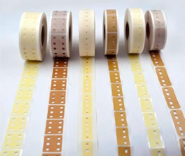
AI Radial Splicing Tape (3-hole / 5-hole, masking or kraft paper)
AI radial splicing tape for vertical auto-insertion machines: 3-hole and 5-hole (6-hole on request), masking or kraft paper, high-tack, die-cut both faces, plus a 12.7 / 15.0 mm radial tape splice cutter.

SMT Feeder Calibration Jig
Check feeder pick-up position, feeding movement and alignment before the feeder goes back on the SMT line. CCD camera, LCD monitor, X/Y/H adjustment, FUJI NXT fixture. 220 V, 45 kg - all values marked with their source.
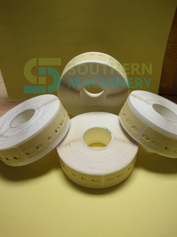
SCT AI Splice Tape for THT Radial Taped Components
High-viscosity AI splice tape for THT radial taped components (capacitors, inductors, diodes) on 12.7 mm and 15.0 mm tape. Masking or kraft paper, die-cut 3/5/6-hole patterns, no residual glue, +15% feeding efficiency. SCT series from Shenzhen Southern Machinery.
Request a quote for S-300B Radial Lead Molding and Taping Machine
Send your board, component list or machine model and we reply with a configuration and quotation. Prices are quoted per project.