
SMT Feeder Calibration Jig
SMT Feeder Calibration Jig for Smart EMS PCB Assembly
Check feeder pick-up position, feeding movement and alignment before the feeder goes back on the SMT line. CCD camera, LCD monitor, X/Y/H adjustment, FUJI NXT fixture. 220 V, 45 kg - all values marked with their source.
Most placement defects that look like machine problems start in the feeder. This jig gives your maintenance team one bench station where the feeder is mounted, the pick-up position is viewed on a monitor, and the alignment is confirmed before the feeder goes back into the machine.
A closely related page covers the same feeder calibration bench: SMT Feeder Calibration Jig for FUJI NXT (S-FFCJ10) (Feeder & Nozzle Service Equipment).
Key features
Pick-up offset that looks like a machine fault
A worn or repaired feeder can present the component slightly off. On the machine that reads as a placement shift or an alignment problem, and the investigation starts in the wrong place.
Throw and jam rates that move with the shift, not the part
When a feeder feeds inconsistently, the line reacts by slowing down or stopping. The cost lands as downtime and rework, and both are attributed to the product rather than to the feeder.
Second-hand feeders that were never checked on arrival
Purchased or traded feeders arrive with unknown history. Without an incoming check, the first production board is the acceptance test, and the failures it produces are paid for twice.
Maintenance that is repeated instead of recorded
When a feeder is returned to service on a verbal handover, the next technician repeats the same check from scratch. A bench station with a written procedure turns that into a record.
Cross-checking that depends on whoever is on shift
Judging a feeder by eye, against a tape hole, under shop lighting, is a different test on every shift. A camera, a cross reference and a fixed procedure make the same judgement repeatable.
A machine problem that is actually a feeder problem
Separating the two quickly is worth more than either fix. A jig does not repair feeders; it makes the diagnosis shorter.
Specifications
Figures as published in Southern Machinery documents. Where two sources disagree, both values are shown with their source.
| Product model name | SFCJF1 FUJI SMT Feeder Calibration Jig (packing list, quotation file) · FUJI NXT feeder calibration jig (manual and product sheet) · Machine name plate: feeder calibration jig · To be confirmed as the current public model naming |
|---|---|
| Purpose | Feeder calibration jig for FUJI NXT feeders · Feeder pick-up position and feeding accuracy check before line use · - · Confirmed use, to be confirmed per machine model |
| Working voltage | 220 V / AC 50 Hz, 60 W · 220 V / AC 50 Hz, 60 W · One source states 110 / 220 V AC, 50 / 60 Hz, 60 W · To be confirmed - two voltage options appear in the sources |
| Machine material | Aluminium and iron · Not stated · - · To be confirmed |
| Working air pressure | 5 kg/cm2 · Not stated · - · To be confirmed - confirm whether pneumatic supply is required and in which units |
| CCD camera magnification | 50X · 50X CCD camera stated in the box list · - · To be confirmed |
| Lighting system | Ring LED lighting · Not stated · - · To be confirmed |
| Display system | Ultra-bright colour LCD display · 7 inch LCD monitor stated in the box list · One product image states a 12 inch colour LCD monitor · To be confirmed - the sources state two different screen sizes |
| Feeder control zones | 8 x 2 mm / 12 x 4 mm / 16 x 8 mm / 24 x 8 mm · Not stated · - · To be confirmed - confirm the meaning of each zone before use |
| Adjustment axes | X, Y, H three-axis adjustment with high-accuracy wheel-gear drive · X / Y and focal adjustment shown on the annotated product image · - · To be confirmed for the current mechanism |
| Lever simulation | Electric drive with single and continuous strike lever simulation of machine movement · Single or continuous strike simulation stated in the manual · - · To be confirmed for the current configuration |
| Calibration reference | Standard calibration ruler to adjust component centre; cross cursor checking on the monitor · Calibration ruler and cross cursor checking stated · - · To be confirmed - the reference supplied with the current package |
| Machine size | 500 x 350 x 550 mm · 350 x 500 x 550 mm · - · To be confirmed - two orientations of the same numbers appear |
| Machine weight | 45 kg · 45 kg · Packing list states net 13 kg / gross 40 kg · To be confirmed - the packing list and the machine weight disagree |
| Export packing size | Not stated · Not stated · 650 x 460 x 510 mm, 0.1525 CBM · To be confirmed for current export packing |
| Box contents | Not stated · Machine unit, LCD monitor, CCD camera, calibration ruler, user manual · - · To be confirmed for the current standard package |
| Machine operation | Key operation · Described as a step-by-step procedure with monitor observation · - · To be confirmed |
In detail
Four things a maintenance technician can actually see
The jig is an observation and adjustment station. It does not repair a feeder and it does not test placement quality. What it does is put the feeder in a repeatable state so four specific things can be seen and adjusted rather than guessed.
- Pick-up position. The position the nozzle takes the component from, viewed through the camera against a cross reference or calibration ruler.
- Feeder pitch and feeding movement. Whether the feeder advances one pitch consistently, and whether the lever or thimble movement behaves the same way on every cycle.
- Tape guide condition. Wear and damage on the tape guide cover, which is a common cause of unstable feeding long before it becomes a placement fault.
- Alignment against the feeder base. Whether the feeder body itself sits square on the fixture, which separates a bent feeder from a misadjusted feeder.
From feeder on the bench to feeder back on the line
The manual describes the procedure as a fixed sequence. This is that sequence, in the order the technician performs it.
- Confirm the feeder. Check the feeder series, the tape width and the pitch against the fixture before mounting anything.
- Mount on the jig base. Seat the feeder on the feeder foundation and clamp it so it cannot shift while the camera is focused.
- Focus and zero the reference. Set the camera focus and align the cross reference on the monitor to the calibration ruler or master reference.
- Advance and observe. Step the feeder forward, watch the pick-up position on the monitor, and use single or continuous lever simulation to observe repeated cycles.
- Adjust X, Y or H. Correct the supported adjustment points, then re-check rather than adjusting more than once and hoping.
- Re-check before release. Run the feeder again through the same observation and confirm the position holds across repeated cycles.
Three things decide whether it works in your maintenance room
A calibration jig is only useful if it accepts the feeder you actually own, holds it in the position the machine expects, and gives your technician a reference they can read the same way twice. Each of those is a configuration question, answered before a price is quoted.
- The feeder series it accepts. The jig base and its sub-bases determine which feeder families can be mounted. The published sheet names a set of feeder control zones; the exact accepted list is confirmed against your feeder part numbers.
- The fixture that positions it. A repeatable bench check needs the feeder to sit in the same place every time. The feeder foundation and the locating pins are what turn a judgement into a measurement.
- The reference the technician reads. The monitor cross reference and the calibration ruler are the reference. Whichever reference is supplied has to be the one your written procedure names, or the procedure is worthless.
- Power and air at the bench. The product sheet states a working voltage and an air pressure requirement. Both belong on the quote, because a bench without the right supply is a bench that does not get used.
- Where it sits in your feeder population. A jig earns its place next to the feeder repair bench, in incoming inspection, or in the spare-feeder store. Which one depends on how many feeders you run and how often they come back.
- What it does not cover. It does not verify placement accuracy on the machine, it does not replace the machine calibration routine, and it does not cover feeder types outside the confirmed list. Those are separate jobs.
Where the documents disagree, both values stay on the page
A specification table that quietly picks one of two numbers is worth less than one that shows both. The items below do not agree across the source documents, or are stated in only one of them. Confirm each against the current drawing for your configuration before you place an order.
What you choose when you order
Each of these is a documented part of the bench station rather than a custom engineering project, and each one changes what the jig can accept.
- Feeder base and sub-bases. The base that holds the feeder square, plus the sub-bases that let different feeder families be mounted in a repeatable position.
- LCD monitor. The screen the technician reads. Screen size is one of the open points on this page and is confirmed before quotation.
- CCD camera with magnification. The observation head. The published magnification is 50X, to be confirmed for the current build.
- Ring LED lighting. The illumination around the observation point, which is what makes a tape hole and a cross reference readable on the monitor.
- Calibration ruler or master reference. The reference the cross cursor is aligned to. The supplied reference has to match the one named in your written procedure.
- Single or continuous lever simulation. Electric drive that simulates machine lever movement, in single strike or continuous mode, so repeated cycles can be observed.
- User manual and training. Written operating procedure, plus remote or on-site guidance for the technicians who will actually run the bench.
Six steps from feeder on the bench to feeder released
The manual describes the procedure as a sequence, and the sequence is the deliverable. A jig without a written procedure is a camera on a desk.
- Scope and safety. Bench work only, on a de-energised feeder outside the machine. This page is not authorisation to service, adjust or operate a placement machine.
- Send your feeder details. A feeder that is out of alignment does not announce itself. It presents as a placement fault, so the process engineer changes a recipe, the operator changes a nozzle, and the real cause stays in the maintenance room until someone puts the feeder on a bench and looks at it directly.
Videos
Clips from the Southern Machinery YouTube channel. Nothing loads from YouTube until you press play.
Catalogues and documents
- PDFSMT Feeder Calibration jig - product brochureFeeder calibration documents
- PDFFeeder Calibration Jig Operation ManualFeeder calibration documents
- 3DMachine catalogue boardContinue browsing
- 3DYouTube video boardContinue browsing
- 3DFeeder catalogue and feeder family pagesRelated feeder material
- PDFBelt feeder brochureRelated feeder material
- PDFBelt feeder scope of useRelated feeder material
Engineering notes
Note 01The placement fault that is really a feeder fault
When the same component drifts on one lane and not another, the recipe is rarely the answer. Full articles are in English. The summary above carries the argument in your language. A line runs three shifts. On the night shift a particular lane starts throwing components, and the morning shift finds the placements…
Note 02What actually happens to a feeder after a repair
A returned feeder is not a restored feeder until somebody has looked at it. Full articles are in English. The summary above carries the argument in your language. A feeder comes off the machine after a jam, a crash or a scheduled strip. It goes to the repair bench, something is replaced or cleaned, and it goes back…
Note 03Second-hand feeders are an incoming inspection problem, not a production problem
The cheapest feeder in the market is one that fails on your line instead of on the supplier's bench. Full articles are in English. The summary above carries the argument in your language. A batch of second-hand feeders arrives. Some are clean, some have been opened, some have unknown history and mismatched wear.…
Note 04How to judge whether feeder calibration is even your problem
Some lines have a placement quality problem that no feeder jig will touch. Full articles are in English. The summary above carries the argument in your language. A production manager buys a jig because placement quality is poor. Three months later the quality is the same, because the drift is in the machine, the…
Note 05One bench, one operator: making the check fast enough that people actually do it
A verification step that takes twenty minutes does not survive a busy shift. Full articles are in English. The summary above carries the argument in your language. The most accurate procedure in the world is skipped when the line is behind and the shift is ending. Every maintenance system in every factory has this…
Note 06What a feeder jig does not do, and why that matters when you buy one
The claims you should refuse to hear from any supplier, including us. Full articles are in English. The summary above carries the argument in your language. A feeder calibration jig does not repair feeders, does not verify placement accuracy on the machine, does not replace the machine's own calibration routine, and…
Frequently asked questions
Is it compatible with my machine and feeder?
Compatibility is confirmed against your machine model, feeder series, feeder width and part number before we quote. The jig base and its sub-bases determine what can be mounted, so a feeder part number is the single most useful thing you can send us. We will tell you when the answer is that a different fixture is needed rather than selling the standard one.
Which brand names appear on this page, and does that mean a partnership?
FUJI, Panasonic, Samsung, JUKI and I-pulse appear here only to describe the machines and feeders a jig may be asked to fit. Naming a brand to define an adaptation requirement is not a statement of authorisation, OEM relationship or certification, and we make no such claim.
How accurate is it?
We do not publish an accuracy figure for this jig, because no accuracy value appears in the Southern Machinery documents this page is built from. Third-party manuals state figures for their own machines; those are not a claim about ours. If you need a stated tolerance for acceptance, ask for it in writing before the order and we will confirm what can be committed.
What is in the box?
The operation manual lists a machine unit, LCD monitor, CCD camera, calibration ruler and user manual. The current standard package is confirmed before quotation, including the monitor size, which is one of the open points on this page.
Can you train our technicians?
Yes. Remote guidance for the technicians who will run the bench can be included with the order, and on-site support can be discussed for larger feeder populations. Tell us the technician count and their experience with the machine brand.
What does it cost, and what is the lead time?
Price and lead time depend on the configuration, the destination power requirement, quantity and the current workload. Send your feeder details and we will confirm both against a current quotation. We do not publish historical prices or lead times.
Do you supply the feeders as well?
Yes. The jig is one item in a wider feeder supply, spare parts and maintenance offer, and it can be quoted alongside feeder supply, feeder repair workflow support and full SMT/THT line integration.
Will this reduce our throw rate?
We do not claim a percentage. A feeder out of alignment contributes to throw, and correcting it removes one cause, but throw also comes from the tape, the component, the nozzle, the machine and the environment. Measure your own throw rate before and after on the same feeder family, and let that number decide.
Related products

SMT Feeder Calibration Jig for FUJI NXT (S-FFCJ10)
Southern Machinery SMT feeder calibration jig (S-FFCJ10) for FUJI NXT feeders: 50x CCD imaging, X-Y digital micrometers, master-gauge zeroing, +/-0.25 mm pickup verification, 8/12/16/24 mm control zones. Specification, videos, documents and quote.
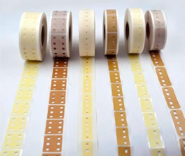
AI Radial Splicing Tape (3-hole / 5-hole, masking or kraft paper)
AI radial splicing tape for vertical auto-insertion machines: 3-hole and 5-hole (6-hole on request), masking or kraft paper, high-tack, die-cut both faces, plus a 12.7 / 15.0 mm radial tape splice cutter.

S-300B Radial Lead Molding and Taping Machine
S-300B radial lead molding and taping machine: forms the lead pitch, tests polarity and value, then tapes 180 plus or minus 20 components a minute, boxed or reeled.
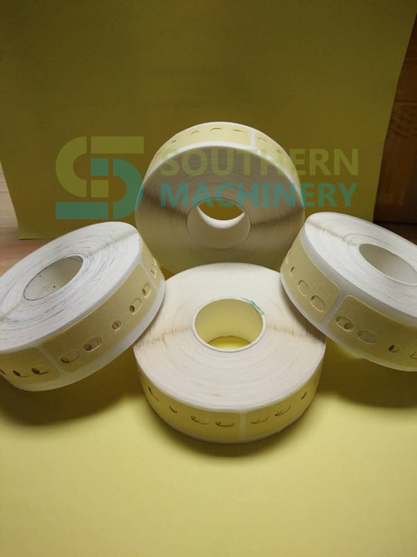
SCT AI Splice Tape for THT Radial Taped Components
High-viscosity AI splice tape for THT radial taped components (capacitors, inductors, diodes) on 12.7 mm and 15.0 mm tape. Masking or kraft paper, die-cut 3/5/6-hole patterns, no residual glue, +15% feeding efficiency. SCT series from Shenzhen Southern Machinery.
Request a quote for SMT Feeder Calibration Jig
Send your board, component list or machine model and we reply with a configuration and quotation. Prices are quoted per project.