
THT-Bestück- und Wellenlötlinie für Handy-Ladegeräte – smarte EMS-Leiterplattenbestückung
THT-Bestück- und Wellenlötlinie für Handy-Ladegeräte
Schlüsselfertige THT-Linie für Leiterplatten von Handy-Ladegeräten und Netzteilen: Platinenlader, Radialbestücker S3010A, Terminal- und Odd-Form-Bestücker S7020, Vier-Kopf-Odd-Form-Zelle mit Wendel- und Schüttgutfeedern, Wellenlötanlage S-WS350 und Auslauf. Interaktive 3D-Linie, Spezifikationen mit Quellen, Videos, Kataloge und Amortisationsrechnung.
Radialkondensatoren, Netzstifte, USB-Steckverbinder, Transformatoren und Drosseln werden maschinell bestückt, dann geht die Platine direkt in die Wellenlötanlage. Ein Lieferant, ein Linienplan, aufgebaut um die Stückliste Ihres Ladegeräts.
- 7
- Stationen im Referenzlayout
- 12,000 CPH
- S3010A radial, veröffentlichter realer Durchsatz
- ±0.05 mm
- Bestückgenauigkeit der Vier-Kopf-Odd-Form-Zelle
- 50–350 mm
- Platinenbreite an der Wellenlötanlage S-WS350
Wichtigste Merkmale
Magazin-Platinenlader
Führt unbestückte oder SMT-bestückte Ladegerätplatinen aus Magazinen in die Linie, sodass niemand am Linieneingang stehen muss.
Radialbestücker S3010A
Bestückt gegurtete Radialbauteile: Elektrolytkondensatoren, Y-Kondensatoren, Folienkondensatoren, LEDs und kleine Induktivitäten, mit Schneiden und Umbiegen im selben Durchgang.
Terminalbestücker S7020T
Zwei Bestückköpfe setzen Netzstifte, Kontakte und Pfosten aus Rollen- oder Wendelfeedern in jedem Winkel in 1°-Schritten.
Odd-Form-Bestücker S7020A
Zwei Köpfe für die Teile, die Radialmaschinen nicht verarbeiten: Sicherungen, Brückengleichrichter, Steckverbinder und Bauteile aus Stangen.
Vier-Kopf-Odd-Form-Zelle S7040
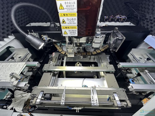
Vier Servoköpfe mit Wendel- und Band-Schüttgutfeedern verarbeiten Transformatoren, Drosseln und USB-Steckverbinder – die Teile, die noch die meisten Hände kosten.
Wellenlötanlage S-WS350
Doppelwellenlöten mit vierstufiger Heißluft-Vorheizung, PC- plus Siemens-SPS-Steuerung und einem Lottopf aus Edelstahl 316.
Auslaufband und Entlader
Kühlt und sammelt gelötete Platinen für Anschlusskürzung, Reinigung, AOI oder die Prüfstation.
Spezifikationen
Werte wie in den Unterlagen von Southern Machinery veröffentlicht. Widersprechen sich zwei Quellen, werden beide Werte mit Quelle gezeigt.
| Speed | 12,000 CPH · S3010A Radial Inserter (PDF) |
|---|---|
| Insertion span | 2.5–10.0 mm (incl. 3.5 mm) · S3010A Radial Inserter (PDF) |
| Component height | ≤ 22 mm · S3010A Radial Inserter (PDF) |
| Feeder inputs | 10–100 · S3010A Radial Inserter (PDF) |
| Reliability | 1000 ppm · S3010A Radial Inserter (PDF) |
| Pre-insertion check | Component value and polarity · S3010A Radial Inserter (PDF) |
| PCB size | 50×50 – 350×250 mm · THT line spec page |
| Dimensions (L×W×H) | 1750 × 1300 × 1600 mm · THT line spec page |
| Speed | 12,000 CPH · S7020 Series brochure 2023 |
| Insertion heads | 2 · S7020 Series brochure 2023 |
| PCB size | 380 × 280 mm · S7020 Series brochure 2023 |
| Terminal thickness | 0.5–1.2 mm · S7020 Series brochure 2023 |
| Insertion angle | 0–360°, 1° steps · S7020 Series brochure 2023 |
| Dimensions (L×W×H) | 1700 × 1300 × 1600 mm · S7020 Series brochure 2023 |
| Insertion heads | 4 · Auto insertion solution (PDF) |
| Feeders | 4 (tape or vibration) · Auto insertion solution (PDF) |
| Speed | 4,000 CPH · Auto insertion solution (PDF) |
| Insertion accuracy | ±0.05 mm · Auto insertion solution (PDF) |
| Component size | 3×3 – 30×30 mm · Auto insertion solution (PDF) |
| Component height | ≤ 50 mm · Auto insertion solution (PDF) |
| PCB size | 50×50 – 300×300 mm · Auto insertion solution (PDF) |
| PCB thickness | 0.8–5.0 mm · Auto insertion solution (PDF) |
| Dimensions (L×W×H) | 1200 × 1100 × 1600 mm · Auto insertion solution (PDF) |
| Weight | 1000 kg · Auto insertion solution (PDF) |
| Power | 220 V AC, 0.8 kVA · Auto insertion solution (PDF) |
| Air pressure | 0.4–0.6 MPa · Auto insertion solution (PDF) |
| Control | PC (Lenovo) + Siemens PLC · S-WS350 brochure |
| PCB width | 50–350 mm · S-WS350 brochure |
| Conveyor speed | 0.5–1.8 m/min · S-WS350 brochure |
| Preheat | 1800 mm, 3 PID zones, hot air, 9 kW · S-WS350 brochure |
| Solder pot | 316 stainless, 18 kW, up to 350°C · S-WS350 brochure |
| Solder capacity | ≈ 380 kg · S-WS350 brochure |
| Waves | 2 (high wave 30 mm, flat 5–12 mm) · S-WS350 brochure |
| Soldering angle | 3–7° · S-WS350 brochure |
| Power | 380 V 3-phase, 19 kW · S-WS350 brochure |
| Dimensions (L×W×H) | 4200 × 1350 × 1650 mm · S-WS350 brochure |
| Weight | ≈ 1200 kg · S-WS350 brochure |
| Dimensions (L×W×H) | 850 × 140 × 260 mm · S-MVF01 brochure |
| Weight | 12 kg · S-MVF01 brochure |
| Component size | 3×3×3 – 20×20×20 mm · S-MVF01 brochure |
8 weitere Zeilen anzeigen
| Typical parts | Connectors, buzzers, terminal posts, square capacitors · S-MVF01 brochure |
|---|---|
| Feeding cycle | 1.5–2 s · S-MVF01 brochure |
| Insertion accuracy | ±1 mm · S-MVF01 brochure |
| Air pressure | 0.4–0.6 MPa · S-MVF01 brochure |
| Commissioning test | 1,000 continuous feeds; 48 h ageing · S-MVF01 brochure |
| Dimensions (L×W×H) | 1150 × 750 × 1350 mm (SLD250) · THT line spec page |
| PCB size | 50×50 – 530×250 mm · THT line spec page |
| Dimensions (L×W×H) | 1550 × 750 × 1350 mm (SUL250) · THT line spec page |
Modelle, Vergleiche und offene Punkte
Which charger part goes on which machine (7 Zeilen)
| Component | Package | Station | Feeding |
|---|---|---|---|
| Electrolytic capacitors (E-cap) | Radial, taped | S3010A | Tape feeder |
| Y-capacitor, film capacitor | Radial, taped | S3010A | Tape feeder |
| AC input pins, terminals | Reel or loose | S7020T | Reel or bowl feeder |
| Fuse, bridge rectifier | Loose or tube | S7020A | Bowl or tube feeder |
| Transformer, common-mode choke | Loose (bulk) | S7040 | Bowl or S-MVF01 bulk feeder |
| USB-A / USB-C connector | Loose or tray | S7040 | Bulk or tray feeder |
| All through-hole joints | PCBA | S-WS350 | Conveyor, titanium fingers |
Where our own documents disagree (10 Zeilen)
| Topic | Figure A | Figure B | How to read it |
|---|---|---|---|
| S3010A speed | 12,000 CPH real throughput (S3010A PDF) | Up to 20,000 CPH (line spec page) | Plan a shift on 12,000; treat 20,000 as a ceiling. |
| S3010A insertion span | 2.5–10.0 mm incl. 3.5 mm (S3010A PDF) | 5–30 mm (line spec page) | Confirm the span for each charger capacitor. |
| S3010A feeder stations | 10 to 100 inputs, scalable (S3010A PDF) | 10 stations (line spec page) | 10 is the base build; more stations are options. |
| S7020T speed | 12,000 CPH (S7020 brochure) | 0.6 s per point (line spec page) | The per-point figure is the realistic planning value. |
| S7020T footprint | 1700 × 1300 × 1600 mm (S7020 brochure) | 1450 × 1300 × 1600 mm (line spec page) | Use the larger figure for floor planning. |
| Odd-form speed | 4,000 CPH, 4 heads (solution PDF) | 0.7 s per part, S7900 (line spec page) | Different platforms; the board decides the real cycle. |
| S-MVF01 feeding cycle | ≤ 1 s (brochure, page 1) | 1.5–2 s (technical parameters) | Size the bulk feeder on 2 s. |
| S-WS350 preheat length | About 2000 mm (feature page) | 1800 mm (spec table) | Same brochure, two pages; confirm on order. |
| S-WS350 pot temperature | Max 300°C (feature page) | Room temp to 350°C (spec table) | Lead-free work sits well below either limit. |
| Model names in the drawing | S350B wave, S7020A odd-form (file name) | S-WS350 wave, S7040 label (brochure, drawing) | Names to be confirmed in the quotation. |
Im Detail
Seven stations from bare board to soldered charger PCBA
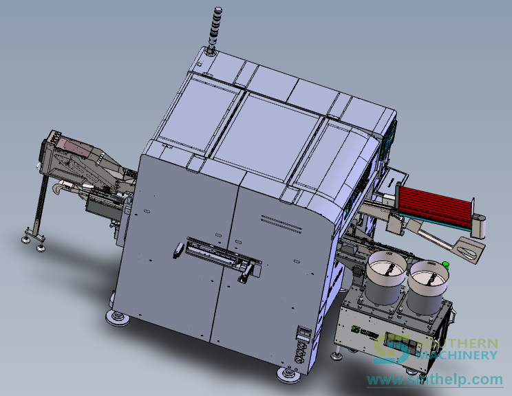
The reference layout below comes from our mobile charger line drawings. The final station count is set from your BOM and takt time, not from a brochure.
- PCB Magazine Loader. Feeds bare or SMT-finished charger boards from magazines into the line, so nobody stands at the line entry.
- S3010A Radial Inserter. Inserts taped radial parts: electrolytic capacitors, Y-capacitors, film caps, LEDs and small inductors, with cut and clinch in the same pass.
- S7020T Terminal Inserter. Two insertion heads place AC pins, terminals and posts from reel or bowl feeders at any angle in 1° steps.
- S7020A Odd-Form Inserter. Two heads for the parts radial machines cannot take: fuses, bridge rectifiers, connectors and tube-packed parts.
- S7040 Four-Head Odd-Form Cell. Four servo heads with bowl and belt bulk feeders handle transformers, chokes and USB connectors, the parts that still cost the most hands.
- S-WS350 Wave Soldering. Dual-wave soldering with four-stage hot-air preheat, PC plus Siemens PLC control and a 316 stainless solder pot.
- Outfeed Conveyor & Unloader. Cools and collects soldered boards for lead cutting, cleaning, AOI or the test stage.
Which charger part goes on which machine
A typical USB charger or adapter board, split by package and feeding method. Your own BOM decides the final split; send it and we return it marked line by line.
Where our own documents disagree
We print both figures rather than pick the flattering one. Plan on the conservative value and let a trial on your board settle it.
Videos
Clips aus dem YouTube-Kanal von Southern Machinery. Von YouTube wird erst etwas geladen, wenn Sie auf Abspielen drücken.
Kataloge und Dokumente
- 3DSouthern-Machinery-YouTube-Video-Board
- PDFS3010A Radial Inserter
- PDFS3010A Radial Machine Automation Solution
- PDFS7020 Series PIN / Eyelet / Terminal Insertion Machine
- PDFS7020 THT Odd Form Insertion Product Description
- PDFShenzhen Southern Machinery Auto Insertion Solution
- PDFS-MVF01 Belt Bulk Feeder
- PDFS-WS350 Wave Soldering Machine
- PDFPCB Loader / Unloader
- PDFS3010A Radial Insertion Machine Operation Manual
- PDFS7020T Terminal Insertion Machine User's Manual
- PDFTHT PCB Design Guideline 2022
- XLSXTHT Insertion ROI Calculator
- 3DSouthern-Machinery-Product-Catalog-Board
- LINKMachine catalog · file.autoinsertion.com
Technische Notizen
The Hidden Ceiling on Hand-Loaded Charger Boards
Your charger line is not slow because people are slow. It is slow because the board waits for hands at the same five parts every cycle. Walk any charger assembly floor at 10 a.m. and count the people bent over insertion benches. On a typical USB charger board, ten to twenty operators place capacitors, pins, a fuse, a…
One Charger Board, Four Ways to Feed It
Feeding decides whether a part can be automated. Here is how each charger component reaches the insertion head. Engineers often ask whether a machine can insert a transformer. Almost always it can. The real question is whether the transformer can arrive at the pick point in the same position every time. On charger…
Why Radial Insertion Comes First on a Charger Line
Capacitors are the most numerous through-hole parts on a charger board. That makes the radial inserter the fastest win. Open a typical USB charger and count its through-hole parts. Electrolytic capacitors, a Y-capacitor, a film capacitor, perhaps an LED and a small inductor: most of them are radial and most of them…
USB Connectors, Transformers and the Parts Hands Still Place
Odd-form parts are where charger lines still spend most of their labour. They are also where a four-head cell pays back fastest. Many charger plants have automated their SMT side and even their radials, yet still keep a bench of operators placing the transformer, the common-mode choke, the fuse and the USB connector.…
Wave Soldering After Auto Insertion: What Changes
Machine-inserted boards arrive at the wave with clinched, consistent leads. That changes how you set up and run the solder process. Wave soldering is where every insertion mistake becomes visible at once: lifted parts, bridged pins, starved joints. On hand-loaded charger boards, the solder operator spends much of the…
Payback on a Charger Line, Using Your Numbers
A payback figure is only useful if every input is yours. Here is a simple way to build one your finance team will accept. A supplier hands over a payback chart showing ten months. Finance asks where the wage figure came from, how many operators are really released and what happens on a short month. The chart has no…
Vollständige Artikel auf der interaktiven Produktseite lesen →
Häufige Fragen
Kann eine Linie sowohl USB-A- als auch USB-C-Ladegerätplatinen verarbeiten?
Ja, wenn die Platinenbreiten zu den Transportbändern passen und jeder Steckverbinder seinen Greifer und Feeder hat. Ein Steckverbinderwechsel ist ein Feeder- und Greiferwechsel, keine neue Maschine. Wir prüfen beide Platinen vor dem Angebot.
Welche Ladegerätbauteile bleiben üblicherweise manuell?
Teile mit leicht verformbaren Anschlüssen, ohne physisches Orientierungsmerkmal oder mit einem Längen-Höhen-Verhältnis unter 1:1,2 eignen sich schlecht für die Schüttgutzuführung. Kabelbäume bleiben ebenfalls meist manuell. Wir markieren sie in Ihrer Stückliste.
Brauche ich die ganze Linie vom ersten Tag an?
Nein. Viele Kunden beginnen mit dem Radialbestücker S3010A oder einer Odd-Form-Zelle und ergänzen später Stationen. Die Transportbänder nutzen SMEMA, neue Maschinen lassen sich also anbinden.
Ist die Wellenlötanlage bleifrei-tauglich?
Die Broschüre der S-WS350 nennt bleifreies und bleihaltiges Lot, einen Lottopf aus Edelstahl 316 und zwei Wellen. Die Profile werden vor Ort mit Ihrem Flussmittel und Ihrer Platine eingestellt.
Wie schnell ist der Support, wenn eine Maschine steht?
Wir antworten innerhalb von 2 Stunden, senden noch am selben Tag einen ersten Plan und innerhalb von 3 Tagen einen Lösungsplan. Ersatzteile werden aus Shenzhen versandt, und unsere Ingenieure reisen für Installation und Schulung an.
Kann ich meine eigene Platine laufen sehen, bevor ich kaufe?
Ja. Senden Sie Muster Ihrer Ladegerätplatine und der Bauteile; wir lassen sie auf den Maschinen laufen und senden Ihnen ein Video sowie einen einseitigen Amortisationsbericht.
Ähnliche Produkte
Radialbestückautomat S3000 für die smarte EMS-THT-Leiterplattenbestückung
Radialbestückautomat S3000 für die THT-Leiterplattenbestückung: gegurtete Radialbauteile mit bis zu 20.000 CPH, Bestückwinkel 0–360 Grad, 10 Feederstationen und Lochkorrektur per Bildverarbeitung.

Axialbestückautomat S4000 für die smarte EMS-THT-Leiterplattenbestückung
Axialbestücker S4000: veröffentlichte Höchstgeschwindigkeit 20.000 CPH, 5–60 modulare Feederstationen, Bestückung in jedem Winkel auf einem Servo-Drehtisch, doppelte Drahtbrücken-Feeder, Platinendicke 0,79–2,36 mm, Platinen 50 x 50 bis 400 x 300 mm. Servoangetrieben, EtherCAT, MES-fähig.
S7900 Odd-Form-Bestückautomat – Lösung für die smarte EMS-THT-Leiterplattenbestückung
Odd-Form-Bestückautomat S7900: 2, 4 oder 6 Servoköpfe, 0,6–0,8 s pro Bauteil, Platinendicke 0,6–2,0 mm, Bestückung 0–360 Grad, vier Umbiegemuster und Wendel-, Gurt-, Stangen- und Trayfeeder auf einer Plattform. Mit Aufteilung einer 36-zeiligen THT-Stückliste und einer Offenlegungstabelle aus drei Dokumenten.
Einige technische Angaben auf dieser Seite (Tabellen, Dokumenttitel) erscheinen wie veröffentlicht auf Englisch.
Angebot anfordern: THT-Bestück- und Wellenlötlinie für Handy-Ladegeräte – smarte EMS-Leiterplattenbestückung
Senden Sie Ihre Platine, Bauteilliste oder Ihr Maschinenmodell, und wir antworten mit einer Konfiguration und einem Angebot. Preise werden projektbezogen kalkuliert.